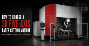
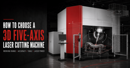
Choosing a 3D five-axis laser cutting machine is fundamentally different from choosing a conventional flatbed laser cutter.
For flat sheet, buyers often begin with relatively straightforward questions:
- What sheet size do we process?
- What material thickness do we cut?
- How much laser power do we need?
For a three-dimensional formed component, those questions are only the beginning.
The cutting head may need to:
- Approach the workpiece from several directions
- Trim curved surfaces
- Cut holes on side walls
- Enter recessed areas
- Rotate around clamps
- Avoid fixture structures
- Maintain suitable nozzle orientation
- Process several part variants on the same machine
This means the correct machine depends on the complete relationship between:
Part geometry + machine travel + cutting-head motion + fixture + worktable + laser process + production strategy
A machine with more travel or more laser power is not automatically the better choice.
A successful selection process starts with the actual component.
1. Start With the Part, Not the Machine Specification
Before comparing five-axis models, prepare a clear description of what the machine must process.
At minimum, define:
- Part type
- 3D CAD model
- Material grade
- Thickness
- Maximum dimensions
- Cutting contours
- Holes and slots
- Required tolerances
- Annual production volume
- Target cycle time
- Number of product variants
This is especially important for components such as:
- Hot-formed automotive parts
- B-pillars
- Door rings
- Crossmembers
- Hydroformed tubes
- Curved sheet-metal panels
- Mold components
- Aerospace parts
- Irregular fabricated structures
ZG Laser’s current five-axis range is organized around different production scenarios rather than one universal machine: automotive hot-formed production, general industrial 3D cutting, small-to-medium batch work, compact production and non-metal applications.
A Better First Question
Instead of asking:
“Do I need a 3000W or 6000W five-axis machine?”
start with:
“What complete three-dimensional cutting task must the machine perform?”
Laser power should be selected later.
2. Build a Part Requirement Matrix
For several product families, create a simple requirement matrix.
| Requirement | Information to Record |
|---|---|
| Part type | B-pillar, panel, tube, mold, structural part |
| Material | Carbon steel, stainless steel, aluminum, etc. |
| Thickness | Minimum / typical / maximum |
| Part size | X × Y × Z overall envelope |
| Fixture size | Approximate footprint and height |
| Cutting features | Trim, holes, slots, bevels |
| Required tolerance | Critical vs general features |
| Annual volume | Parts/year |
| Production rate | Parts/shift or target cycle time |
| Loading | Manual / robot |
| Variants | Number of different parts |
The machine should be optimized around the parts that represent most of your production—not around one rare oversized component.
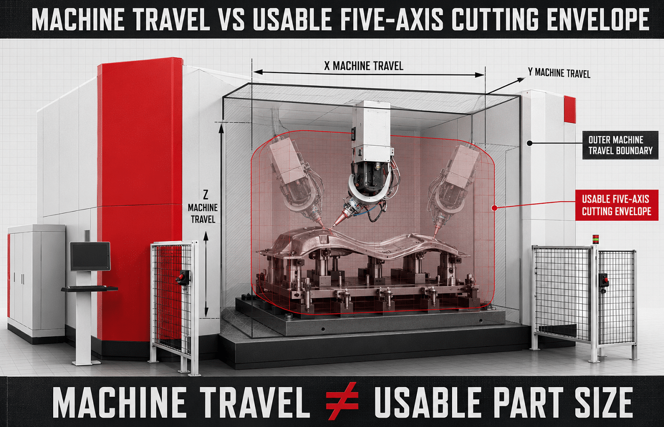
3. Machine Travel Is Not the Same as Usable Part Size
This is one of the most important points in five-axis machine selection.
A specification may state:
- X travel: 4500 mm
- Y travel: 2500 mm
- Z travel: 700 mm
That does not automatically mean a 4500 × 2500 × 700 mm workpiece can be processed in every orientation.
The actual usable part size also depends on:
- Fixture footprint
- Clamp height
- Cutting-head dimensions
- Head tilt
- Rotary-axis geometry
- Machine enclosure
- Lead-in and retract movements
Your current S-Auto page draft already makes this distinction explicitly: the part, fixture and cutting-head clearance must be considered together when confirming the usable cutting envelope.
A better engineering concept is:
Usable Cutting Envelope = Machine Travel − Fixture Constraints − Cutting-Head Clearance − Motion Safety Margin
This is conceptual rather than a literal subtraction formula, but it reflects how the project should be evaluated.
4. Measure the Part Together With the Fixture
Do not send only the part dimensions to the machine supplier.
Consider the part-and-fixture assembly.
For example, a component may measure:
2800 × 900 × 400 mm
but after fixture design the complete installation may occupy:
3300 × 1300 × 650 mm
because the fixture includes:
- Base structure
- Clamps
- Locating pins
- Supports
- Pneumatic components
- Loading clearance
Then add cutting-head movement around the fixture.
The final required machine envelope may be much larger than the raw part dimensions suggest.
5. Evaluate X, Y and Z Travel Separately
X/Y/Z travel determines the linear working envelope.
X-Axis
Usually influences the maximum usable component length.
Important for:
- Long automotive reinforcements
- Door rings
- Large panel parts
- Hydroformed components
Y-Axis
Determines width access.
This becomes important when:
- Fixtures extend beyond the component
- The head must approach from the side
- Two stations share the same worktable
Z-Axis
Z travel is easy to underestimate.
It must accommodate:
- Part height
- Fixture height
- Cutting-head approach
- Retract movement
- Surface variation
A 500 mm-high part on a 250 mm fixture does not automatically fit into a machine with 700 mm Z travel.
The complete kinematic model must be checked.
6. Rotary-Axis Range Determines Cutting-Head Accessibility
A five-axis machine usually adds two rotary movements to X/Y/Z.
ZG Laser’s current fiber five-axis platforms list A-axis travel up to ±135° and continuous multi-turn C-axis capability on several configurations.
The specific axis naming can vary between machine manufacturers.
What matters is whether the cutting head can reach every required surface.
Check Your Most Difficult Features
Do not validate only easy trim contours.
Identify features such as:
- Deep side-wall holes
- Reverse-facing flanges
- Recessed slots
- Sharp surface transitions
- Angled end cuts
- Bevel features
Then simulate the required cutting-head orientation.
More Rotary Range Is Not Automatically Better
A very large rotary range creates no value if your parts do not require it.
What matters is:
Can the machine reach all required cutting features without approaching axis limits or causing collisions?
7. Cutting-Head Accessibility Should Be Simulated Before Order
A five-axis machine can have enough nominal travel but still fail to access one important feature.
Possible causes include:
- Cutting-head body collides with the part
- Clamp blocks the nozzle
- Fixture frame blocks head rotation
- A-axis reaches its limit
- Enclosure restricts the movement
- Required approach angle creates poor gas delivery
This is why a 3D machine selection project should include:
Part model + fixture model + cutting-head model + machine model
before final configuration.
Offline programming and collision simulation
8. Do Not Select the Machine From Working Range Alone
Two five-axis machines may both physically fit the part but be intended for very different production strategies.
For example:
Machine A
- Large work envelope
- Fixed table
- Flexible part loading
- General 3D work
Machine B
- Similar processing envelope
- Automatic rotary table
- Multi-station production
- Higher investment
If the project produces:
20 prototype parts per month,
Machine B may provide little economic benefit.
If it produces:
hundreds of hot-formed components per shift,
the rotary-table architecture can become much more valuable.
Therefore:
Working range determines whether the machine can process the part. Production architecture determines whether it should process the part.
9. How Should Accuracy Be Evaluated?
Accuracy is another specification buyers frequently misinterpret.
A brochure may provide:
- X/Y/Z machining accuracy
- X/Y/Z repeat positioning accuracy
- Rotary-axis machining accuracy
- Rotary-axis repeatability
These are useful machine specifications.
But they are not automatically finished-part tolerances.
ZG Laser’s current five-axis specifications, for example, list X/Y/Z machining accuracy of ±0.05 mm and repeat positioning accuracy of ±0.03 mm for several fiber models.
Those values describe machine-axis performance.
The finished component also depends on:
- TCP calibration
- Rotary-axis calibration
- Fixture repeatability
- Formed-part variation
- Cutting parameters
- Kerf compensation
- Measurement method
Your existing five-axis accuracy article explains this distinction in detail.
Do Not Ask Only:
Ask:
“Can the complete process repeatedly meet the critical tolerances on my actual component?”
10. Define Critical Tolerances Before Selecting the Machine
Not every feature requires the same tolerance.
Separate the drawing into:
Critical Features
Examples:
- Assembly locating holes
- Bolt holes
- Welding interfaces
- Functional trim edges
- Alignment slots
General Features
Examples:
- Clearance openings
- Non-functional trim edges
- Scrap contours
This matters because achieving very tight tolerance everywhere may require:
- More precise fixtures
- More calibration
- More inspection
- More engineering work
The project should optimize accuracy where it creates functional value.
11. Repeatability May Matter More Than One Perfect Sample
A supplier may produce one excellent sample.
That proves feasibility.
It does not necessarily prove production stability.
For repetitive production, evaluate several consecutive parts.
Record:
- Hole position
- Trim location
- Part-to-part variation
- Edge quality
- Cycle time
- Operator intervention
A machine suitable for one prototype is not automatically suitable for mass production.
12. Choose the Worktable According to Production Strategy
The worktable is one of the most important configuration decisions.
Common options include:
- Fixed worktable
- Sliding worktable
- Rotary worktable
- Customized fixture/table systems
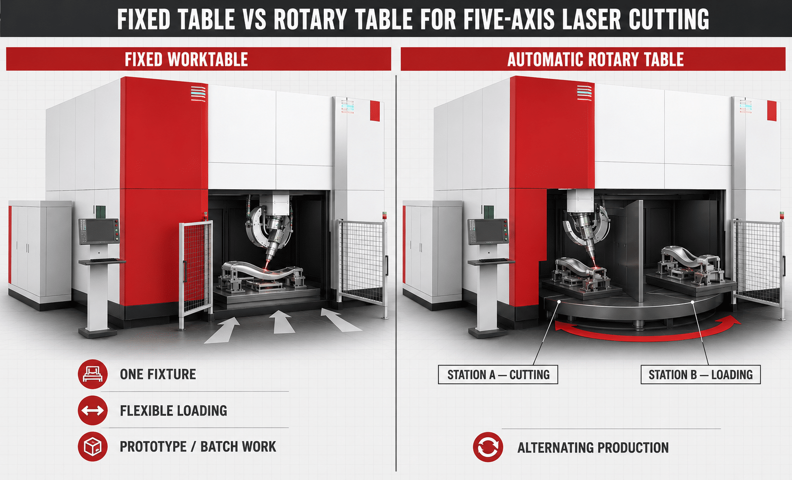
ZG Laser’s current portfolio uses different worktable concepts across its five-axis platforms: the S-Auto family uses an automatic rotary table, DF configurations can use fixed or slide worktables, and SF is positioned around a fixed worktable.
13. When Does a Fixed Worktable Make Sense?
A fixed table is a strong starting point when:
- Production volume is moderate
- Part variety is high
- Loading time is not the main bottleneck
- Fixtures change frequently
- Parts are large
- Prototype work is important
Advantages can include:
- Simpler machine structure
- Flexible fixture layout
- Easier engineering changes
- Lower system complexity
A fixed table does not mean the machine is low productivity.
For parts with long laser-on times, loading may represent only a small share of the total cycle anyway.
14. When Does a Sliding Table Make Sense?
A sliding table can improve loading access or support alternative production layouts.
Possible benefits include:
- Easier operator access
- Moving the fixture into a loading position
- Simplified handling of large components
The actual benefit depends on the specific table mechanism and machine layout.
Ask:
- How far does the table travel?
- Can loading occur while cutting continues?
- How does table movement affect cycle time?
- How is the fixture referenced after movement?
Do not assume “slide table” means the same thing on every machine.
15. When Should You Choose an Automatic Rotary Table?
A rotary table becomes particularly attractive in repetitive production.
The concept is simple:
Station A: Cutting
while simultaneously:
Station B: Unload finished part + load next part
Then the table indexes.
This reduces the amount of time the cutting machine waits for the operator.
ZG Laser’s S-Auto platform uses an automatic rotary-table architecture and is positioned around automotive hot-formed parts and high-cycle production.
Your current S-Auto configuration draft lists 4,000 mm and 5,000 mm table diameters for its two machine sizes, with single-side load capacities of 350 kg and 500 kg respectively.
Rotary Table Is Valuable When
- Annual volume is high
- Loading time is significant
- Dedicated fixtures are used
- Part mix is stable
- Operators can prepare the next station during cutting
- Robot loading is planned
Rotary Table May Be Unnecessary When
- Batch size is very small
- Fixtures change constantly
- Cutting time is short but inspection dominates
- Parts are difficult to load quickly
- Part size makes rotation inefficient
16. Table Positioning Time Is Not Production Cycle Time
This distinction matters when reviewing brochures.
A rotary table may index very quickly.
That does not mean the complete part cycle is equally short.
The actual production cycle includes:
Loading + Positioning + Clamping + Table Indexing + Piercing + Cutting + Head Repositioning + Unclamping + Unloading
Your current S-Auto technical draft already includes a note that table positioning time should not be interpreted as total cutting or production cycle time.
Always request:
complete part cycle time
rather than one motion-system speed.
17. Check Worktable Load Capacity
Large automotive fixtures can become heavy.
The table must support:
- Fixture
- Part
- Clamps
- Pneumatic hardware
- Protection plates
For multi-station tables, verify whether the specification refers to:
- Total table load
- Per-side load
- Per-fixture load
Do not compare only table diameter.
A larger fixture may physically fit but exceed permissible load or reduce machine dynamics.
18. Choose Laser Power After the Machine Architecture
ZG Laser’s current fiber five-axis portfolio offers 3000W, 4000W and 6000W configurations across several product families.
But power selection should come after you have established:
- Part geometry
- Working range
- Fixture
- Worktable
- Production requirements
Why?
Because laser power primarily affects the cutting process.
It does not solve:
- Insufficient machine travel
- Poor head accessibility
- Wrong fixture strategy
- Slow loading
- Incorrect table architecture
19. Do Not Choose Laser Power by Thickness Alone
Material thickness matters, but it is only one variable.
Power selection should consider:
- Material grade
- Thickness
- Coating
- Hole quantity
- Hole diameter
- Cutting length
- Piercing requirements
- Head orientation
- Edge quality
- Assist gas
- Target cycle time
Two parts made from the same thickness can require different configurations.
Example
Part A
- Long simple trims
- Few holes
- Moderate cycle requirement
Part B
- Dozens of small holes
- Multiple head angles
- Frequent piercing
- High-volume automotive production
The same nominal thickness does not make them the same laser application.
20. 3000W vs 4000W vs 6000W: How Should You Think About It?
Do not publish a universal thickness table for these three powers unless it has been validated for the exact machine, material and process.
A better buyer-guide framework is:
3000W
May be evaluated where:
- Material thickness is moderate
- Cycle-time demand is lower
- Product geometry dominates the process more than cutting speed
- Capital cost needs to be controlled
4000W
May offer a useful middle configuration when:
- Production speed requirements increase
- Material mix is broader
- More process margin is required
6000W
May deserve evaluation when:
- Higher throughput is important
- Material or thickness demands more cutting capacity
- Piercing time matters
- The production volume can justify the additional system cost
These are evaluation directions, not fixed material capability limits.
The final choice should be validated through sample testing.
21. Higher Laser Power Does Not Automatically Mean Shorter Total Cycle Time
Suppose laser power reduces actual cutting time from:
60 seconds to 45 seconds.
But the complete cycle also requires:
- 35 seconds loading
- 8 seconds clamping
- 12 seconds repositioning
- 30 seconds unloading and inspection
The improvement in total productivity is much smaller than the raw cutting-speed improvement suggests.
This becomes especially important in 3D processing because:
- Head orientation changes take time
- Piercing may dominate some features
- Part loading is more complex
- Fixtures require clamping
Compare total cycle time, not maximum laser speed.
22. Assist Gas Is Part of the Power Decision
Typical fiber-laser cutting gases include:
- Oxygen
- Nitrogen
- Compressed air
ZG Laser’s DF and SF five-axis specifications currently list air, nitrogen and oxygen as applicable assist gases.
Gas selection affects:
- Cutting speed
- Edge oxidation
- Dross
- Operating cost
- Downstream coating or welding
A 6000W machine operated with expensive nitrogen is not automatically more economical than a lower-power configuration using a different validated process.
Evaluate cost per acceptable finished part.
Laser Cutting Assist Gas: Oxygen vs Nitrogen vs Compressed Air
23. Machine Speed and Acceleration Matter—but Read Them Correctly
Five-axis brochures may list:
- Maximum X/Y/Z speed
- Rotary-axis speed
- Acceleration
These indicate machine dynamic capability.
They do not directly equal production speed.
ZG Laser currently lists maximum linear-axis speeds of up to 100 m/min for some five-axis configurations and 80 m/min for others, with A/C-axis speeds up to 540°/s on several fiber platforms.
But real cutting involves:
- Corners
- Rotary motion
- Head orientation
- Piercing
- Process-speed limits
Therefore:
maximum axis speed is a machine capability specification—not a guaranteed part-production rate.
24. Evaluate Machine Dynamics on the Actual Path
A long straight rapid movement benefits from high linear speed.
A small complex automotive component may instead require:
- Frequent direction changes
- Short movements
- A/C rotations
- Small holes
In this case:
- Acceleration
- Servo response
- rotary-axis motion
- CAM path optimization
may influence cycle time more than top linear speed.
Ask the supplier to run your complete part program when cycle time is important.
25. Software Is Part of the Machine Configuration
For 3D five-axis cutting, offline programming is not an optional convenience for complex production.
It is a core engineering capability.
The programming system should support functions such as:
- 3D CAD import
- Cutting-path generation
- Cutting-head orientation
- Fixture modeling
- Collision simulation
- Machine kinematics
- NC generation
- Process parameters
ZG Laser’s current five-axis product page lists offline programming, five-axis control and process-parameter settings among the system capabilities for complex 3D geometries.
Ask What “Software Included” Actually Means
Confirm:
- Which CAD formats are supported?
- Can the fixture be imported?
- Can full machine collisions be simulated?
- Are rapid moves checked?
- Is a machine-specific postprocessor included?
- Can the software estimate cycle time?
- Is training included?
- Is the license permanent or recurring?
Offline Programming and Collision Simulation for 3D Five-Axis Laser Cutting
26. Safety Enclosure and Dust Extraction Should Be Selected With the Application
Five-axis systems process parts at different orientations.
This can change the direction of:
- Sparks
- Slag
- Smoke
Evaluate:
- Full enclosure
- Safety doors
- Observation windows
- Dust extraction
- Fire protection
- Slag management
ZG Laser currently offers safety enclosure and dust-extraction options according to system configuration.
The correct configuration depends on:
- Material
- Cutting power
- Part geometry
- Destination-market requirements
- Factory safety standards
27. Manual Loading or Automated Loading?
Automation should solve a production bottleneck.
Manual Loading May Be Suitable When
- Production volume is moderate
- Parts change frequently
- Prototype work is common
- Components are light enough
- Operators need flexibility
Automated Loading May Be Suitable When
- Production is repetitive
- Components are heavy
- Rotary-table production is used
- Cycle time is important
- Multiple shifts are planned
A five-axis machine can also be combined with a separate handling robot.
This allows:
five-axis machine = cutting
and:
robot = loading/unloading
The production cell should be designed around the full cycle rather than machine capability alone.
28. Do You Need a Five-Axis Machine or a Robotic Laser Cell?
Before ordering a dedicated machine, very large or highly variable parts should also be evaluated against robotic cutting.
A dedicated five-axis machine generally provides:
- Defined machine workspace
- Machine-tool architecture
- Controlled repeat production
- Integrated worktables
A robotic system may provide:
- Larger flexible reach
- Multiple stations
- Greater layout flexibility
- Easier adaptation to very different part sizes
Neither is universally superior.
29. Select the Machine Series by Production Scenario
For the current ZG Laser portfolio, a practical selection logic is:
| Production Scenario | Starting Platform |
|---|---|
| Automotive hot-formed parts / high-cycle production | S-Auto Series |
| General industrial 3D parts / larger flexible processing | DF Series |
| Prototype / small-to-medium batches | SF Series |
| Smaller parts / limited workshop space | Compact Five-Axis |
| Non-metal 3D processing | CO₂ Five-Axis |
| Extremely large or highly variable 3D components | Also evaluate robotic laser cutting |
ZG Laser’s current collection page positions the series in broadly these application groups.
30. S-Auto Series: When Should You Consider It?
The S-Auto architecture is intended for repetitive automotive 3D trimming.
Typical applications include:
- Hot-formed parts
- Automotive structural components
- Internal high-pressure tubes
- B-pillars
- Reinforcements
The current product family uses:
- Automatic rotary worktable
- Large 3D working envelope
- 3000 / 4000 / 6000 W fiber-laser options
- Five-axis A/C head motion
ZG Laser currently lists approximately 3500–4500 mm X travel, 2100–2500 mm Y travel and 700 mm Z travel across the S-Auto range.
The main purchasing question is not:
“Is S-Auto the highest-spec machine?”
It is:
“Does my production volume justify a dedicated rotary-table automotive architecture?”
31. DF Series: When Is a General-Purpose Platform Better?
DF is positioned toward broader industrial 3D processing.
Applications listed by ZG Laser include:
- General 3D metal parts
- Panel parts
- Automotive trial production
- Mold manufacturing
- Hardware
- Aerospace-related processing
Current configurations use fixed or sliding worktable layouts and approximately 4000–4500 mm X travel, depending on model.
DF may be a better starting direction when:
- Product mix is broader
- High-cycle rotary production is unnecessary
- Large 3D working range is still required
- Fixture flexibility is important
32. SF Series: When Does a Value-Engineered Machine Make Sense?
SF is positioned toward:
- Prototype testing
- Small-to-medium batch production
- Mold processing
- Flexible product development
The current machine architecture uses a fixed table and 3 / 4 / 6 kW fiber-laser configurations.
It may be appropriate when the buyer needs true five-axis capability but does not need the more production-oriented architecture of an automotive rotary-table system.
This can be particularly relevant for companies entering 3D laser cutting for the first time.
33. Compact Five-Axis: Do Not Buy a Large Machine for Small Parts
Large working range is not free.
It can increase:
- Machine footprint
- Equipment investment
- Factory requirements
- Fixture size
- Motion distances
ZG Laser’s current compact platform lists approximately:
1500 × 1500 × 700 mm X/Y/Z travel
with 3000–6000W fiber-laser options.
If your workpieces are consistently small, a compact system may provide a more rational production footprint.
Do not buy 4.5 meters of X travel simply because it looks more capable.
34. Fiber Five-Axis vs CO₂ Five-Axis
Do not assume every five-axis laser machine is designed for metal.
ZG Laser also lists a CO₂ five-axis platform for materials such as:
- Wood
- Paper
- Leather
- Textiles
- Acrylic
- Plastic
- Rubber
- Crystal
- Bamboo
The current CO₂ configuration is fundamentally different from the 3–6 kW fiber-metal systems and is listed at 200W in the current product table.
Select laser technology according to material first.
Do not compare only the number of axes.
35. Factory Footprint Must Be Evaluated Early
A machine that fits the part may not fit the workshop.
Include space for:
- Machine
- Electrical cabinet
- Laser source
- Chiller
- Dust collector
- Gas supply
- Operator area
- Fixture loading
- Maintenance access
- Robot loading, if applicable
ZG Laser’s DF and SF specifications show that complete machine footprints can reach several meters beyond the nominal cutting travel.
Always request a complete installation-layout drawing before order.
36. Confirm Utilities Before Finalizing the Configuration
Depending on machine configuration, prepare for:
- Electrical power
- Assist gas
- Compressed air
- Cooling
- Dust extraction
- Network connection
- Environmental requirements
Do not wait until the machine arrives to discover that:
- Nitrogen supply is insufficient
- Factory power needs upgrading
- Extraction ducting does not fit
- Access doors cannot accommodate the machine modules
Utilities belong in the purchasing decision.
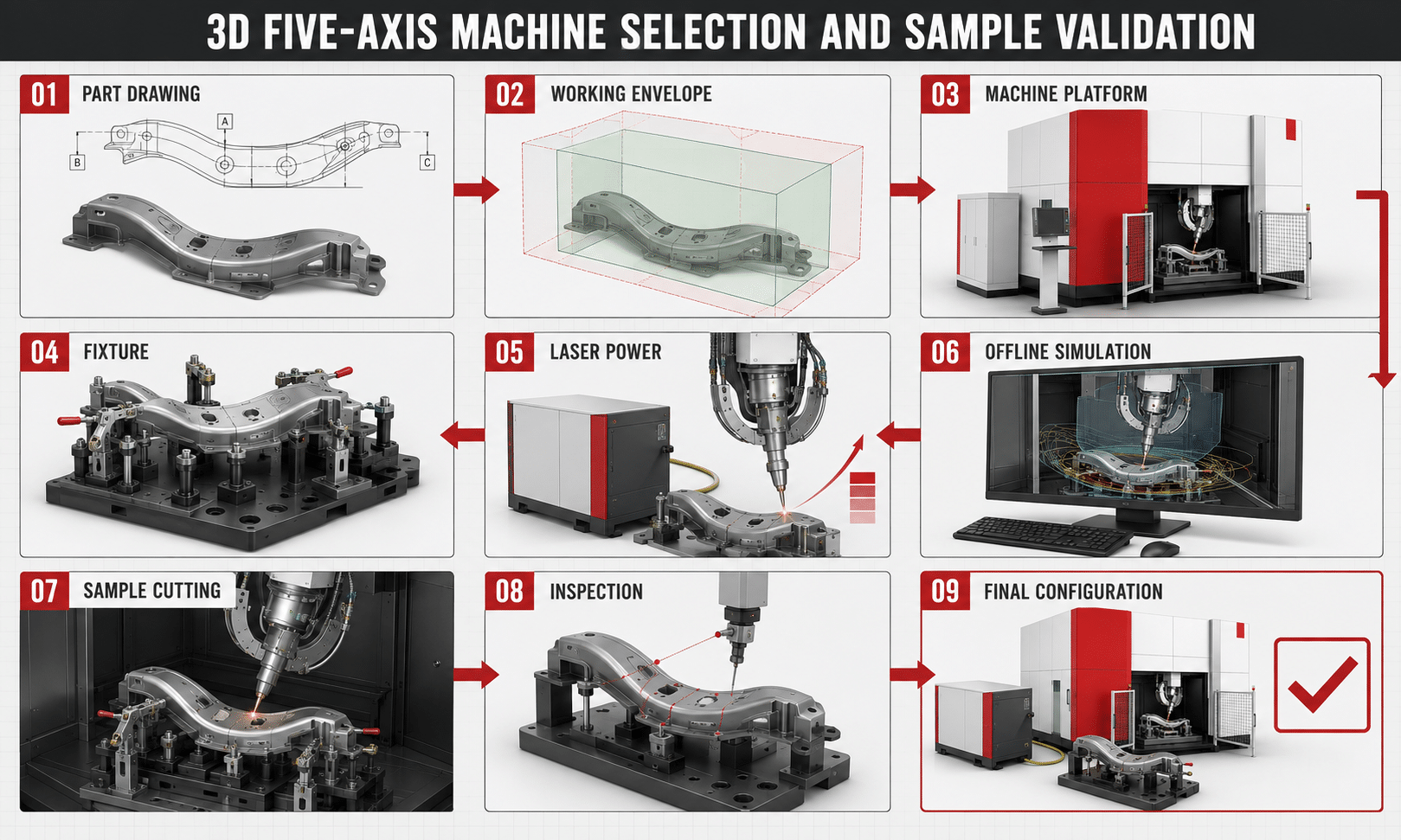
37. Sample Cutting Should Be Required for Critical Projects
For a serious five-axis project, catalog comparison should lead to sample validation.
Provide the supplier with:
- Actual formed part
- 3D CAD
- 2D drawing
- Material
- Thickness
- Critical tolerances
- Target cycle time
The Test Should Verify
- Head accessibility
- Fixture strategy
- Edge quality
- Hole quality
- Trim position
- Cycle time
- Part loading
- Repeatability
ZG Laser’s current project-evaluation process likewise recommends drawing review, configuration review and sample cutting for critical projects.
38. Test the Most Difficult Feature, Not the Easiest Feature
If the component contains:
- One deep recessed hole
- One difficult side-wall trim
- One tight fixture clearance
- Twenty simple contours
the difficult feature should drive feasibility testing.
A supplier demonstration showing only an easy external cut does not prove the machine can process the complete part.
Include:
- Maximum head angle
- Deepest feature
- Smallest hole
- Tightest tolerance
- Most difficult access area
in the test program.
39. Agree on the Inspection Method Before Testing
Do not wait until after sample cutting to decide whether the result passes.
Agree in advance on:
- Inspection datums
- Free-state or fixture-state measurement
- CMM / checking fixture / scanner
- Critical features
- Acceptance tolerance
- Number of samples
This prevents situations where:
the supplier measures from one datum,
while:
the customer later measures from another.
40. Define FAT Around the Part, Not Only the Machine
Factory Acceptance Testing should include machine checks.
But for a custom 3D production project, part-level validation is often more meaningful.
Possible FAT items include:
Machine
- Axis operation
- Safety
- Laser
- Control
- Software
Application
- Correct fixture
- Program execution
- Critical dimensions
- Edge quality
- Repeated parts
- Cycle time
Documentation
- Training
- Software
- Parameters
- Maintenance
- Acceptance report
Do not allow an application-specific machine to be accepted only because the axes move correctly.
41. Compare Total Project Cost, Not Only Machine Price
Five-axis system cost can include:
- Machine
- Laser source
- Cutting head
- Offline programming software
- Fixture
- Rotary or sliding table
- Dust extraction
- Safety enclosure
- Installation
- Training
- Sample development
- Automation
Operating cost can include:
- Electricity
- Assist gas
- Nozzles
- Protective lenses
- Maintenance
- Labor
- Fixture maintenance
The relevant metric is:
Cost per acceptable finished part
not:
Machine price per kilowatt
42. A More Expensive Architecture Can Be Cheaper in Production
Consider two machines.
Machine A
Lower purchase price, but:
- Manual loading
- Longer waiting time
- One station
- Frequent operator intervention
Machine B
Higher purchase price, but:
- Rotary table
- Parallel loading
- Stable dedicated fixture
- Shorter complete cycle
For high-volume production, Machine B may have the lower cost per part.
For small batches, Machine A may be the better investment.
This is why machine architecture should follow annual production volume.
43. Questions to Ask a Five-Axis Laser Machine Supplier
Before finalizing an order, ask:
- Can the machine process my complete 3D part?
- Has the full part-and-fixture envelope been checked?
- What X/Y/Z travel is required?
- What usable cutting envelope remains after fixture installation?
- Can the head reach every required feature?
- What A/C-axis ranges are required?
- Have rotary limits been simulated?
- What machine-axis accuracy is specified?
- How is TCP calibrated?
- What finished-part tolerance can be demonstrated?
- Which worktable is recommended?
- Why is a fixed, sliding or rotary table recommended?
- What is the maximum fixture/table load?
- Which laser power is recommended?
- Why is that power appropriate?
- Which assist gas is recommended?
- What is the estimated complete cycle time?
- Which offline programming software is included?
- Is collision simulation included?
- Can the posted NC program be verified?
- What safety enclosure is included?
- What extraction is required?
- Can robot loading be integrated?
- What factory utilities are required?
- Can my actual part be sample tested?
- How will the sample be measured?
- Can repeated parts be tested?
- What FAT criteria will be agreed?
- What installation and training are included?
- What service and spare-part support is available?
A good supplier should explain:
why the recommended configuration fits your part and production strategy.
44. Final Five-Axis Machine Selection Checklist
Before placing the order, confirm:
- Actual 3D CAD reviewed
- Material confirmed
- Thickness confirmed
- Maximum part dimensions confirmed
- Fixture envelope estimated
- X/Y/Z travel checked
- Complete head accessibility simulated
- A/C-axis travel verified
- Deep features checked
- Critical tolerances identified
- Accuracy terminology understood
- Fixture strategy agreed
- Worktable architecture selected
- Worktable load checked
- Production volume confirmed
- Target cycle time confirmed
- Laser power validated
- Assist gas selected
- Software scope confirmed
- Collision simulation confirmed
- Safety enclosure confirmed
- Extraction confirmed
- Factory footprint confirmed
- Utilities confirmed
- Automation requirement defined
- Sample cutting completed
- Critical dimensions inspected
- Multiple parts tested where required
- Complete cycle time measured
- FAT criteria documented
- Final configuration written into the technical agreement
Conclusion
Choosing a 3D five-axis laser cutting machine should not begin with laser power.
It should begin with the part.
The correct selection sequence is:
Part geometry
→ usable cutting envelope
→ cutting-head accessibility
→ required accuracy
→ fixture strategy
→ worktable architecture
→ production volume
→ laser power
→ software and automation
→ sample validation
A large machine with a high-power laser can still be the wrong solution if:
- The fixture blocks an important cutting angle
- The table architecture does not match production volume
- The software cannot efficiently program complex parts
- Final part tolerance cannot be demonstrated
Likewise, a smaller or lower-power configuration can be the better investment when it matches the real production task.
The most important buying principle is:
Choose the complete production system—not the most impressive individual specification.
For a critical five-axis project, the final machine should therefore be selected only after the supplier has evaluated:
- Actual 3D geometry
- Fixture
- Cutting path
- Required tolerances
- Production volume
- Target cycle time
and, where practical, verified the configuration through representative sample cutting.
Choose the Right Five-Axis Configuration for Your Part
Send ZG Laser:
- Your 3D CAD model
- 2D drawing
- Material
- Thickness
- Maximum dimensions
- Required tolerances
- Annual production volume
- Target cycle time
- Automation requirements
Our application team can evaluate:
- Required machine travel
- Cutting-head accessibility
- Fixture concept
- Worktable configuration
- Laser power
- Offline programming requirements
- Sample-testing plan
before recommending a final machine configuration.
Frequently Asked Questions
How do I choose the right 3D five-axis laser cutting machine?
Start with the actual part geometry, material, thickness, required tolerances, production volume and target cycle time. Then evaluate machine travel, cutting-head accessibility, worktable, fixture, laser power and software as one complete system.
Is machine travel the same as maximum workpiece size?
No. Fixture dimensions, cutting-head tilt, clamps, machine structure and required safety clearance reduce the usable processing envelope.
How much five-axis working range do I need?
Choose enough X/Y/Z travel to cover the complete part, fixture and cutting-head movement. Avoid significantly oversizing the machine unless future production requirements justify it.
How important are the A and C rotary axes?
They determine whether the cutting head can reach angled and curved surfaces. Actual accessibility should be checked using the part, fixture and machine model.
Does ±0.05 mm machine accuracy mean my finished part will be within ±0.05 mm?
No. Machine-axis accuracy is only one contributor. Final part accuracy also depends on calibration, fixture repeatability, workpiece variation, programming, cutting conditions and measurement. ZG Laser’s current five-axis specifications use ±0.05 mm as an X/Y/Z machine-axis accuracy value on several configurations.
Should I choose a fixed or rotary worktable?
A fixed table is often suitable for flexible or smaller-batch production. A rotary table becomes attractive when high-volume production allows loading and unloading at one station while cutting occurs at another.
Is an automatic rotary table always faster?
Not necessarily. Productivity depends on the complete cycle, including loading, clamping, cutting and unloading. Fast table indexing alone does not determine output.
Should I choose 3000W, 4000W or 6000W?
Select power according to material, thickness, cutting features, edge requirements and target cycle time. ZG Laser currently offers these three power levels on several fiber five-axis platforms, but the correct choice should be validated on representative parts.
Is higher laser power always better?
No. Higher power does not increase working range, improve fixture design or solve head-access problems. It also may not significantly reduce total cycle time when loading, piercing or multi-axis movement dominates production.
What is the best five-axis machine for automotive hot-formed parts?
A production-oriented system with suitable working envelope, accurate fixtures and efficient loading should be evaluated. ZG Laser currently positions its S-Auto platform specifically for hot-formed automotive structural components and rotary-table production.
When should I choose a compact five-axis machine?
A compact configuration can make sense when workpieces are smaller, workshop space is limited and the larger working range of a full-size machine would provide little production benefit.
Do I need offline programming software?
For complex 3D parts, offline programming and collision simulation are highly valuable because head orientation, fixtures and machine motion should be verified before production.
Should I perform sample cutting before ordering?
For critical applications, yes. Representative sample cutting allows you to verify accessibility, edge quality, dimensional results, fixture strategy and cycle time before the final machine configuration is confirmed.
What information should I send for a quotation?
Provide the 3D model, 2D drawing, material, thickness, maximum dimensions, required cutting features, tolerances, annual volume, target cycle time and automation requirements.