
Flexible six-axis 3D laser processing
3D RoboticLaser Cutting Machine
A project-engineered six-axis robotic fiber-laser cell for multi-angle trimming, punching and profiling of curved panels, shaped tubes and complex structural parts.
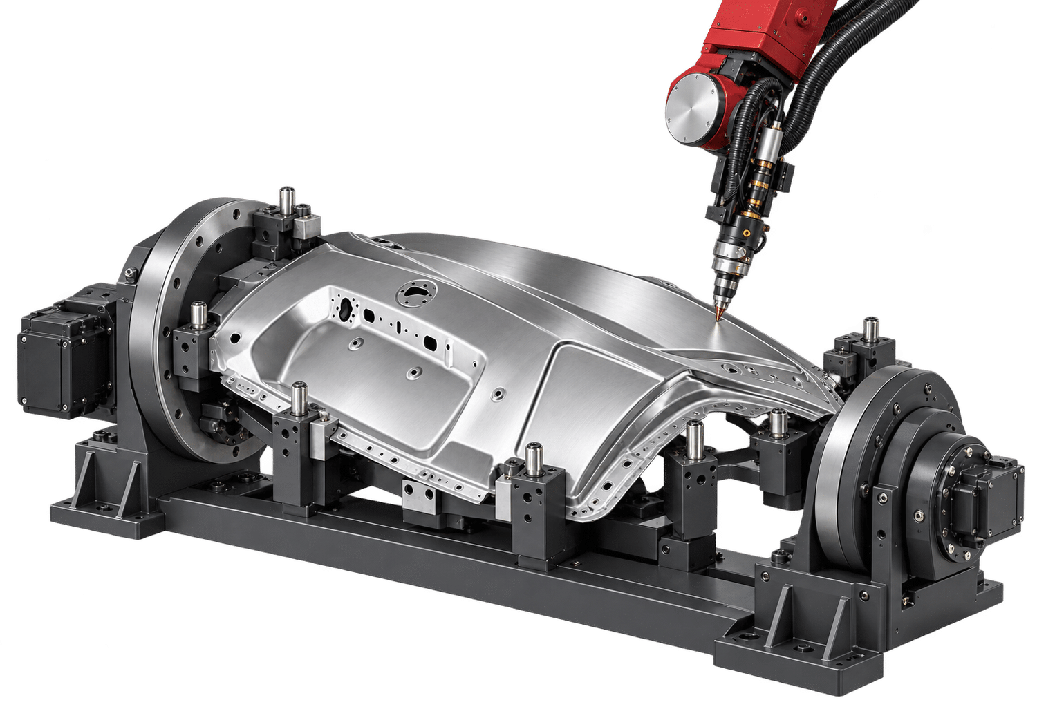
Multi-angle robot motion
Contact-free processing
Fixture, reach and automation engineered per project
01 / Project-engineered robotic cell
Follow complex geometry.
Reach more cutting angles.
The cell combines an industrial six-axis robot with a fiber-laser cutting head to process three-dimensional parts that are difficult to reach on a flatbed machine.
- Trim edges and openings on curved sheet-metal components.
- Cut shaped tubes and irregular structural parts from multiple orientations.
- Match the robot, fixture, positioner, laser source, software and guarding to the actual production task.
Robot brand, reach, payload and installation orientation are selected for the part envelope.
Laser power and cutting head are selected around material, thickness and cut-quality criteria.
Fixed, rotary or multi-station workholding can be engineered for accessibility and takt time.
No single numeric configuration applies to every robotic cell. Final reach, payload, power, accuracy, cycle time, dimensions, safety and acceptance criteria are confirmed after drawing review and simulation.
02 / Core capabilities
Flexible motion for
complex three-dimensional parts.
The finished cell is configured around representative CAD data, access angles, material, batch mix and target output.
Six-axis flexibility
Approach curved and irregular parts from multiple angles for three-dimensional cutting paths.
Fiber-laser integration
Configure the source and compact robot-mounted cutting head for the target material and thickness.
Trim, punch and profile
Combine perimeter trimming, hole cutting and contour profiling within one programmed cell.
Offline programming
Plan paths and evaluate reach, posture and potential collisions before production.
Vision and calibration
Add visual positioning, calibration and seam/location compensation when the process requires it.
Cell automation
Integrate fixtures, positioners, loading, extraction, guarding and line controls around the production route.
03 / Machine details
Robot, fixture and process
engineered as one cell.
These images show typical project concepts; the delivered configuration follows the approved technical agreement.
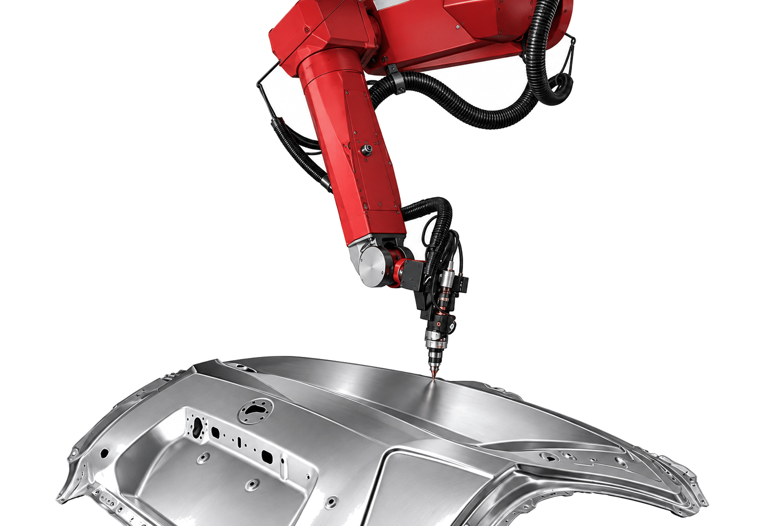
Six-axis arm and cutting path
The articulated robot carries the cutting head around curved panels and irregular geometry.
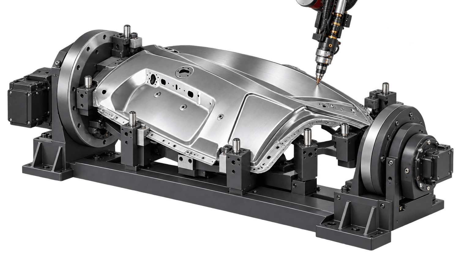
Fixture and rotary positioner
Project-specific workholding supports access, repeatability and efficient loading.
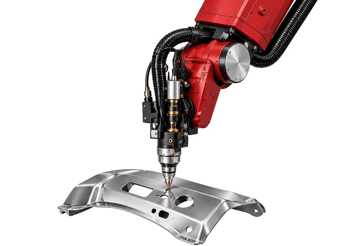
Compact fiber-laser cutting head
A robot-mounted head follows programmed 3D paths for trimming, punching and profiling.
Have 3D CAD data? Send the part and cell requirements ↗
04 / Applications
Complex parts across
industrial production.
Final suitability depends on geometry, material, thickness, access, fixture strategy and acceptance criteria.
Confirm the cell with representative parts. Provide 3D CAD, material, thickness, maximum envelope, fixture datum, required cuts, batch size, target takt time and plant layout.
05 / Configuration
One custom model.
Many engineered cell options.
Select the robot, laser, cutting head, fixture, positioner, software and safety system around the actual part family.
| Parameter | Available configuration |
|---|---|
| Product type | Custom robotic 3D fiber-laser cutting cell |
| Motion platform | Six-axis industrial robot |
| Laser source | Fiber laser |
| Processing functions | Trimming, punching and profiling |
| Typical workpieces | Curved panels, shaped tubes and complex structural parts |
| Robot brand / model | Selected for the approved reach, payload and service requirements |
| Robot reach / work envelope | Configured after CAD, fixture and access-angle review |
| Robot payload | Matched to cutting head, dress pack and auxiliary equipment |
| Laser output power | Selected by material, thickness, quality and cycle-time targets |
| Cutting head | Compact robot-mounted fiber-laser head configured for the process |
| Fixture / positioner | Fixed, rotary, multi-axis or multi-station options |
| Offline programming | Available; path simulation and reach review configured by project |
| Visual positioning | Optional according to part variation and locating strategy |
| Calibration | Robot, tool center point, fixture and process calibration defined by project |
| Positioning / repeatability | Confirmed with the selected robot, fixture, calibration and acceptance method |
| Loading method | Manual, assisted or robotic loading according to project scope |
| Controls / integration | PLC, safety controls and production-system interfaces configured as required |
| Guarding / extraction | Laser-safe enclosure or fence, interlocks and fume extraction engineered for the cell |
| Utilities / dimensions / weight | Finalized for the approved cell layout and technical agreement |
06 / Project evaluation
From 3D part data
to an accepted robotic cell.
Build the configuration around representative parts and measurable acceptance criteria.
Part and CAD review
Share 3D CAD, material, thickness, part envelope, datum strategy, required cuts, batch mix and target output.
Cell and fixture engineering
Select robot reach and payload, cutting head, power, fixture, positioner, guarding, extraction and loading route.
Offline simulation and trial
Check reach, posture and collisions, then validate representative parts and cycle assumptions.
Technical agreement and FAT
Freeze components, layout, utilities, software, safety, training and acceptance scope before delivery.
07 / Common questions
Before you configure
a robotic cutting cell.
Confirm the part family, access, workholding, output and acceptance method before locking the equipment.
How is a robotic cell different from a dedicated five-axis machine?
A robot offers a flexible work envelope and cell layout for varied three-dimensional parts. A dedicated five-axis platform may provide a more fixed machine envelope and production architecture. Select after part, accuracy, access and volume review.
What parts can it process?
Typical projects include curved automotive panels, shaped tubes, irregular structures and formed components requiring trimming, punching or profiling from multiple angles.
How is laser power selected?
Power is selected from material, thickness, piercing demand, edge quality, assist gas and cycle-time target; it is not fixed for every custom cell.
Can a positioner be added?
Yes. Fixed fixtures, rotary positioners, multi-axis positioners and multi-station workholding can be evaluated for access and throughput.
Is offline programming available?
Yes. Offline programming, path simulation, reach review and collision checking can be configured; visual positioning is optional.
How is accuracy confirmed?
Accuracy is defined for the complete system, including robot, tool center point, fixture, calibration, part variation and inspection method, then frozen in the technical agreement.
What should I send for a recommendation?
Send 3D CAD, material and thickness, maximum part envelope, required cuts, fixture datum, annual volume, target takt time, loading concept and factory layout.
08 / Tell us about the part and cell
Turn your 3D part data
into a robotic cutting plan.
Share representative CAD, material, cut features and production targets. ZG Laser can review reach, fixture, positioner, power, software and safety.
- 3D CAD, material, thickness and maximum part envelope
- Trim edges, holes, profiles, datum and inspection requirements
- Batch mix, annual volume and target takt time
- Loading concept, floor space, guarding and available utilities
Request a project review
Start with the essentials. Fields marked * are required.
For CAD files, describe what you have and ask the team for the appropriate submission method.