
Structural steel profile processing
I-BeamLaser Cutting Machine
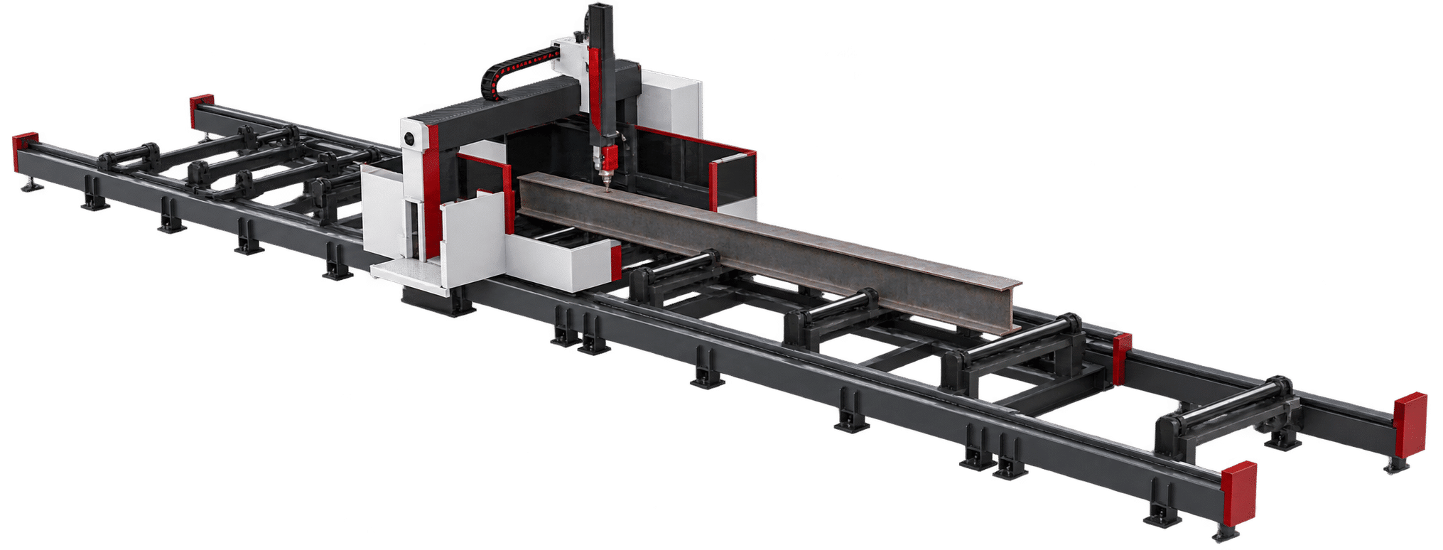
A project-engineered fiber-laser system for cutting, piercing, beveling, marking and cutoff of long I-beams, H-beams, channels and angles.
Published ZG-BC laser power options
Ground-track support for long beams
Reduced loading and unloading interruption
01 / Project-engineered profile system
Process flange, web and end features in one digital workflow.
The system combines a long segmented support line, gantry cutting station and profile-specific handling to turn structural-steel models into ready-to-fit components.
- Cut holes, slots, contours and end profiles on flanges and webs.
- Prepare straight or beveled edges for fit-up and welding.
- Match working length, profile range, power, handling and software to the fabrication route.
I-beam, H-beam, channel, angle and compatible profiles are evaluated from drawings and standards.
Fiber laser, vertical or bevel-capable head and extraction are selected for the cut plan.
Rollers, supports, centering, clamps, loading and unloading are configured around beam size and weight.
The published ZG-BC configuration includes 12 kW and 20 kW options, ground-track support for beams up to 15 m long and 1.5 m wide, dual workstations, contour detection and centering. Other ranges and components remain project-configurable.
02 / Core capabilities
One line for structural profiles and fabricated joints.
The final process is configured around representative profiles, drawings, joint features, material, throughput and plant layout.
Flange and web processing
Reach the principal faces of structural profiles for coordinated holes, slots, contours and trimming.
Holes, slots and contours
Create connection holes, access openings, notches and project-defined shapes directly from digital files.
Bevel and cutoff
Configure bevel-capable processing for weld preparation, miters and finished profile ends.
Weld-position marking
Add reference marks and assembly information where the approved process requires them.
Centering and support
Use rollers, lifting supports, centering and clamps to stabilize long and heavy profiles through the cell.
Model-driven production
Connect nesting and structural-steel model data to path planning, simulation and production management.
03 / Machine details
Cutting station, handling and software engineered as one line.
The images show typical project concepts; the delivered configuration follows the approved technical agreement.
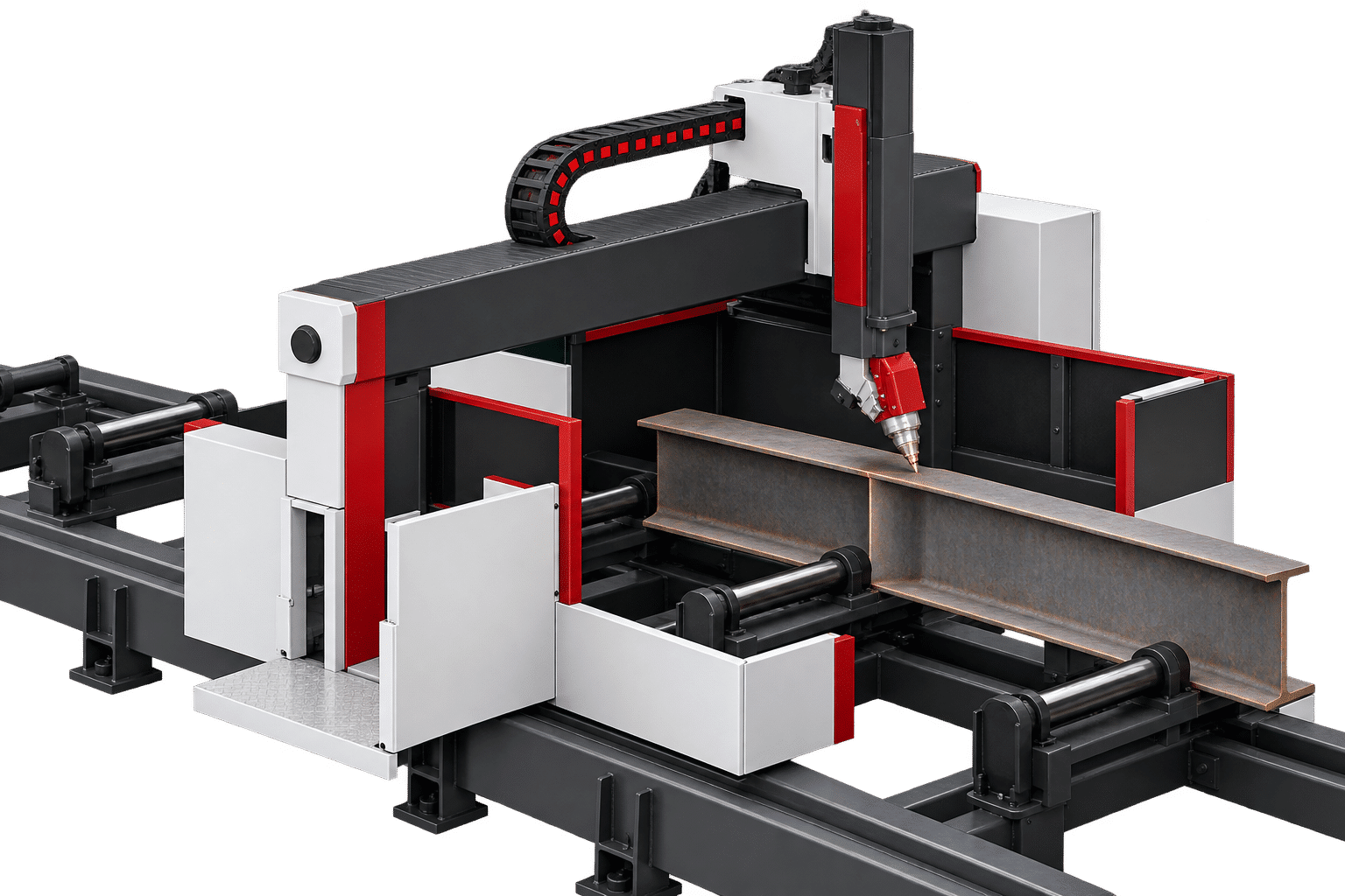
Gantry and process head
A rigid gantry carries the fiber-laser head across the profile while the support line manages long workpieces.
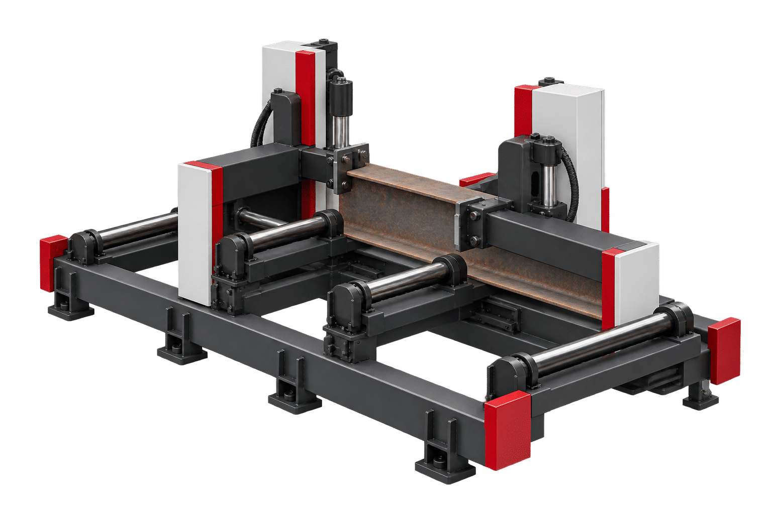
Roller support and centering
Project-specific rollers, lifting supports and centering devices locate the beam and reduce unsupported span.
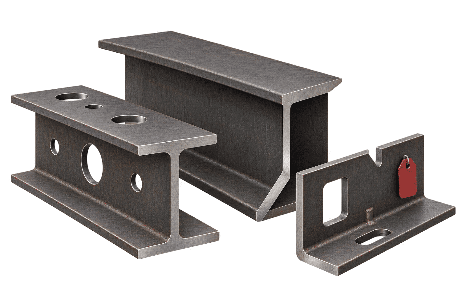
Profile holes, cutouts and bevels
Digital cutting combines connection holes, slots, copes, end contours and weld-preparation features.
Have a Tekla model or beam drawings? Send the profile schedule and cut features ↗
04 / Applications
Structural components for heavy fabrication.
Final suitability depends on profile geometry, material, thickness, length, weight, cut access and acceptance criteria.
Confirm the line with representative profiles. Provide profile standards and sizes, material grades, lengths, weights, drawings or 3D models, cut features, annual volume and plant layout.
05 / Configuration
Published ZG-BC capability with project-specific options.
Start from the published 12/20 kW, long-beam and dual-workstation architecture, then finalize the complete configuration around actual production data.
| Parameter | Available configuration |
|---|---|
| Product series | ZG-BC Series |
| Product type | Structural-profile fiber laser cutting system |
| Supported profiles | I-beam, H-beam, channel, angle and compatible structural profiles |
| Published laser power | 12 kW / 20 kW; other power levels can be evaluated for the project |
| Published laser source brands | IPG or Raycus; final source and component brands are confirmed in the technical agreement |
| Published maximum beam length | Up to 15 m with the ground-track support configuration |
| Published maximum section width | Up to 1.5 m in the referenced ZG-BC configuration |
| Workstation arrangement | Dual-workstation design; handling and station layout can be customized |
| Main processes | Cutoff, bevel cutting, hole cutting, contour cutting and laser marking |
| Flange and web processing | Configured according to profile geometry, face access and required features |
| Contour detection | Supported to compensate for profile dimensional variation |
| Centering system | Centering device for profile location and material-deformation compensation |
| Long-beam support | Ground-track support, rollers and auxiliary supports configured for the approved beam range |
| CAD / software | TEKLA workflow and SolidWorks-file compatibility are published; other interfaces are confirmed by project |
| Cutting head | Vertical or bevel-capable configuration according to the approved process scope |
| Bevel capability | Required faces, joint geometry and angle range are confirmed in the technical agreement |
| Loading / unloading | Manual, trolley, conveyor or automatic handling options |
| Laser safety | Enclosed processing area, interlocks, emergency stop and project-specific protective devices |
| Fume management | Extraction and ventilation engineered for the material, power and installation |
| Controls / integration | PLC, production data and upstream/downstream interfaces configured as required |
| Accuracy / cycle time | Defined for representative profiles and the agreed FAT acceptance method |
| Utilities / dimensions / weight | Finalized in the quotation, layout and technical agreement |
06 / Project evaluation
From beam schedule to an accepted production line.
Build the configuration around representative profiles and measurable acceptance criteria.
Profile and drawing review
Share section standards, size range, material, length, weight, joint details, cut features, batch mix and output target.
Line and handling engineering
Select the cutting station, power, head, supports, centering, loading, unloading, extraction, guarding and floor layout.
Nesting and sample validation
Review model import, paths, collision risks and representative samples before freezing the process.
Technical agreement and FAT
Confirm components, software, utilities, training and measurable acceptance criteria before delivery.
07 / Common questions
Before you configure an I-beam cutting line.
Confirm the profile family, feature access, handling route, software and acceptance method before locking the equipment.
How is this different from a standard tube laser cutter?
An I-beam system is engineered for large structural sections, long and heavy material, flange-and-web access, profile-specific supports and fabrication features such as copes, connection holes, bevels and assembly marks.
Which profiles can it process?
Typical projects include I-beams, H-beams, channels and angles. Exact standards, dimensional ranges, straightness and weight must be checked from the profile schedule.
Can it cut both the flange and web?
Yes, the cutting concept can be designed to reach flange and web features. Access to each face and feature is confirmed from drawings and simulation.
Is bevel cutting available?
A bevel-capable head can be configured for weld preparation and angled end features. Required faces, joint geometry and angle range must be frozen in the technical agreement.
Can it work with Tekla models?
The existing ZG-BC page publishes TEKLA support and SolidWorks-file compatibility. Confirm software versions, import formats and nesting workflow during project evaluation.
How are long and heavy beams handled?
Rollers, lifting supports, centering, clamps, trolleys, conveyors and automatic loading or unloading can be combined according to beam length, weight and factory layout.
What should I send for a recommendation?
Send profile standards and sizes, material grades, length and weight ranges, 2D drawings or 3D models, required cut features, annual volume, shift target and available floor space.
08 / Tell us about the profile schedule
Turn structural drawings into a cutting-line plan.
Share representative profiles, joint details and production targets. ZG Laser can review range, handling, laser power, bevel process, software and safety.
- Profile standards, material grades, size, length and weight range
- Holes, slots, copes, end contours, bevels and marking requirements
- 2D drawings, Tekla/IFC/STEP model and nesting workflow
- Batch mix, target output, floor space and material-flow direction
Request a project review
Start with the essentials. Fields marked * are required.
For drawings or larger files, describe what you have and ask the team for the appropriate submission method.