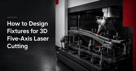
A high-precision five-axis laser cutting machine does not automatically produce an accurate finished component.
The machine can follow the programmed path correctly while the final trim line or hole position is still wrong if the workpiece is:
- Located differently between cycles
- Clamped into a distorted shape
- Supported incorrectly
- Loaded against unstable surfaces
- Positioned from the wrong datum
- Blocked by clamps or fixture structures
For this reason, fixture design is a fundamental part of a 3D laser cutting project.
This is particularly important for:
- Hot-formed automotive components
- Stamped panels
- Hydroformed tubes
- Castings
- Curved sheet-metal parts
- Welded assemblies
- Aerospace components
- Irregular 3D workpieces
A good fixture must solve several problems at the same time.
It must:
- Locate the component consistently.
- Support the component without unnecessary deformation.
- Hold it securely during loading and cutting.
- Leave enough space for five-axis cutting-head movement.
- Allow sparks, molten material and fumes to escape safely.
- Support efficient loading and unloading.
- Remain repeatable after hundreds or thousands of production cycles.
Traditional fixture-design principles remain useful. Carr Lane identifies accurate referencing, repeatable locating and avoiding redundant location as fundamental workholding principles, while Renishaw’s fixturing guidance similarly uses the 3-2-1 principle to establish stable primary, secondary and tertiary datums.
However, 3D laser cutting adds another requirement that conventional machining fixtures do not always face to the same degree:
The fixture must leave a clear three-dimensional movement envelope around the entire laser cutting head.
This guide explains how to design around all of these requirements.
1. What Is the Main Purpose of a Five-Axis Laser Cutting Fixture?
A fixture has three main functions:
Locate
It establishes the position and orientation of the workpiece relative to the machine coordinate system.
Support
It prevents the component from sagging, rocking or changing position under gravity, clamping or part release.
Hold
It keeps the component against the intended locating points during the cutting cycle.
These functions should not be confused.
A clamp should not be used to compensate for poor locating.
A support should not accidentally become an uncontrolled datum.
And adding more contact points does not automatically improve accuracy.
The fixture should create a clear and repeatable relationship:
Machine → Fixture → Workpiece → Cutting Path
If that relationship changes, the cut changes even when the CNC program remains identical.
What determines 3D five-axis laser cutting accuracy
2. Start With the Finished-Part Drawing, Not the Fixture
A common mistake is to start fixture design by asking:
“Where can we put the clamps?”
The better question is:
“Which features determine how this component functions and how it will be inspected?”
Before designing the fixture, review:
- 3D CAD model
- 2D drawing
- GD&T information
- Assembly datums
- Critical holes
- Trim tolerances
- Joining interfaces
- Measurement method
- Incoming part variation
The fixture datum strategy should generally relate to the functional datum system of the component.
Example: Automotive B-Pillar
Suppose a B-pillar contains:
- Two assembly locating holes
- Several welding holes
- An external trim contour
- A flange with a looser tolerance
If the assembly holes are functionally critical, the fixture should not be designed around an unstable flange simply because it is convenient to clamp.
Otherwise, forming variation at that flange may shift every critical cut feature.
Prioritize Features
Separate the drawing into:
Critical features
- Assembly locating holes
- Bolt holes
- Welding interfaces
- Functional trim edges
- Datum surfaces
General features
- Clearance openings
- Non-critical exterior trims
- Scrap contours
This helps determine where positional accuracy matters most.
3. Understand the 3-2-1 Locating Principle
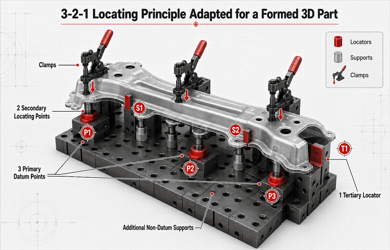
The classical 3-2-1 locating principle is a useful starting point for fixture design.
In a simplified rigid workpiece:
- Three points establish the primary datum plane.
- Two points establish the secondary datum.
- One point establishes the tertiary datum.
Together, they establish the workpiece position and orientation.
Renishaw’s fixture guidance describes the same structure using three primary contacts, two secondary contacts and one tertiary contact for repeatable fixturing.
Carr Lane likewise describes the 3-2-1 method as a basic approach for controlling workpiece movement through six properly selected locating points.
But Do Not Apply 3-2-1 Blindly
A large hot-formed sheet-metal component is not the same as a rigid machined block.
The part may contain:
- Curved surfaces
- Flexible flanges
- Large unsupported spans
- Variable forming geometry
Additional support points may therefore be necessary.
The key distinction is:
Additional supports do not necessarily need to become additional datums.
You can support a flexible area without allowing every support to independently determine the part position.
Otherwise, the fixture can become over-constrained.
4. Choose Stable Datum Features
The best locating surface is not necessarily the largest surface.
It should be the feature that provides the most consistent reference between parts.
Possible locating features include:
- Existing holes
- Machined pads
- Formed datum surfaces
- Stable edges
- Dedicated locating features
Holes
Existing holes can provide strong positional references when:
- Their position is controlled upstream
- Hole tolerance is suitable
- They are not distorted during forming
A common approach uses:
- One round locating pin
- One diamond or relieved locating pin
rather than two rigid round pins that can create binding when hole spacing varies.
Surfaces
A formed surface can be used when:
- Geometry is repeatable
- Contact is stable
- The part will not rock
- Surface variation is acceptable
Edges
Edges can be useful, but assess:
- Trim variation
- Burrs
- Forming variation
- Coating
- Wear
Do not locate a precision cutting operation from a feature whose incoming position is less stable than the tolerance you are trying to achieve.
5. Avoid Redundant Location
More locators may appear safer.
In reality, unnecessary locators can reduce consistency.
Carr Lane specifically warns against redundant location, where more than one locator attempts to control the same degree of freedom. Because real production parts vary, they may not contact all redundant locators simultaneously, creating inconsistent seating.
Example
Imagine a curved component supported by four rigid pads intended to define one plane.
If the real component varies slightly:
- Part A contacts pads 1, 2 and 3.
- Part B contacts pads 1, 3 and 4.
- Part C rocks between all four.
The fixture now has several possible seating conditions.
Better Approach
Use:
- Clearly defined primary locators
- Additional support where necessary
- Adjustable or compliant supports where appropriate
The fixture should tell the part exactly where to sit.
It should not give the part several competing answers.
6. Distinguish Locators From Supports
This distinction is especially important for large thin-walled 3D parts.
Locators
Locators define the workpiece position.
Their position should be:
- Accurate
- Stable
- Repeatable
- Wear resistant
Supports
Supports prevent:
- Sagging
- Vibration
- Local deformation
- Movement during loading
They do not always need to define the datum.
Why This Matters
Consider a long formed automotive reinforcement.
Three points may establish its primary reference plane, while several other supports carry flexible sections.
If every support is made rigidly height-critical, normal forming variation may prevent the workpiece from seating properly.
Possible alternatives include:
- Adjustable supports
- Floating supports
- Spring-supported pads
- Replaceable shims
- Profile-matched nests
The correct solution depends on production variation and tolerance.
7. A Fixture Should Locate the Part, Not Force It Into Shape
This is one of the most important principles for formed-part laser trimming.
A component may not match nominal CAD geometry perfectly.
If the fixture uses powerful clamps to force every area against a theoretical surface, the component may appear correct while clamped.
After cutting and unclamping, it can spring back.
The result may then fail inspection.
Excessive Clamping Can Cause
- Flange deformation
- Panel distortion
- Hole-position changes
- False dimensional conformity
- Springback after release
Therefore:
A fixture should locate the production part consistently, not mechanically recreate the CAD model unless the product specification explicitly requires constrained positioning.
This is particularly important for:
- Hot-formed components
- Thin stainless panels
- Aluminum parts
- Large stamped components
TRUMPF’s guidance for secondary processing of formed components specifically identifies securing parts with repeatable positioning while processing them without deformation as a key challenge in this application.
8. Use the Minimum Effective Clamping Force
Laser cutting is a non-contact process.
Unlike milling, drilling or mechanical punching, there is no conventional cutting tool pushing heavily against the workpiece.
Therefore, the fixture usually does not require the same high clamping forces associated with heavy machining.
The clamps primarily need to:
- Maintain contact with locators
- Prevent movement during table motion
- Control vibration
- Maintain position as scrap is released
- Keep the part stable during loading and unloading
Excessive Force Creates More Problems Than It Solves
Too much force can:
- Deform thin sections
- Damage coatings
- Mark visible surfaces
- Increase fixture complexity
- Increase loading time
Clamp Toward the Locator
Where practical, clamping force should push the component:
toward its locating surfaces
rather than sideways away from them.
The locating elements establish position.
The clamp maintains that position.
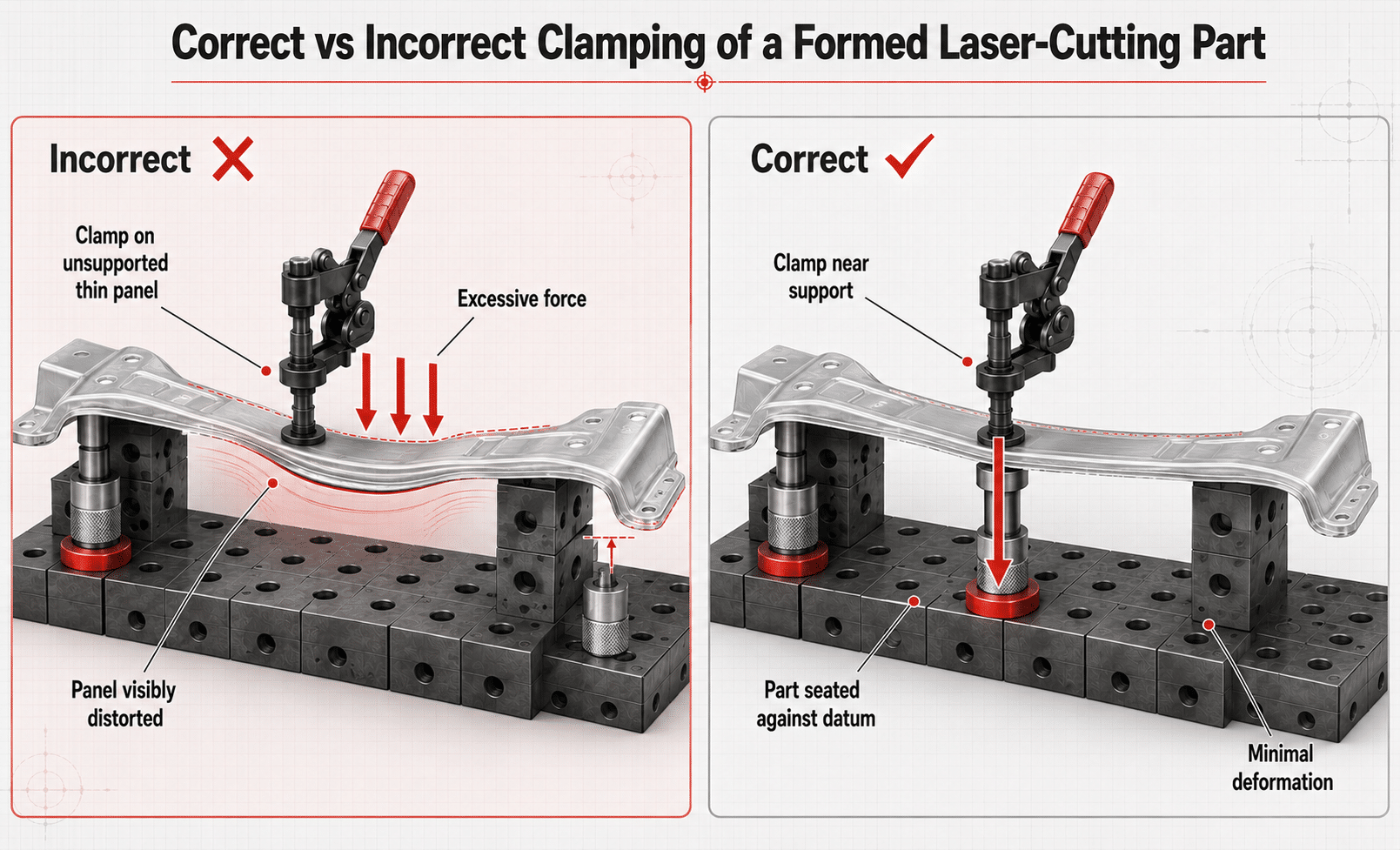
9. Clamp Close to Supported Areas
A clamp pressing on an unsupported flexible surface may bend the part.
Where possible:
Clamp toward a support or locator.
Avoid configurations where:
- Clamp is above a large unsupported span
- Thin flange is squeezed between distant points
- Clamp force creates local bending
Example
Poor design:
Clamp ↓
Thin sheet
Large unsupported gap
Support
This can deform the panel.
Better design:
Clamp ↓
Part
Support directly below or nearby
The clamp then seats the part without unnecessarily bending it.
10. Cutting-Head Accessibility Must Be Designed Into the Fixture
This is where a five-axis laser fixture differs fundamentally from many conventional fixtures.
The cutting head does not simply move vertically above the component.
It may:
- Tilt
- Rotate
- Approach from the side
- Reach underneath a flange
- Follow a curved surface
- Move through several orientations around one feature
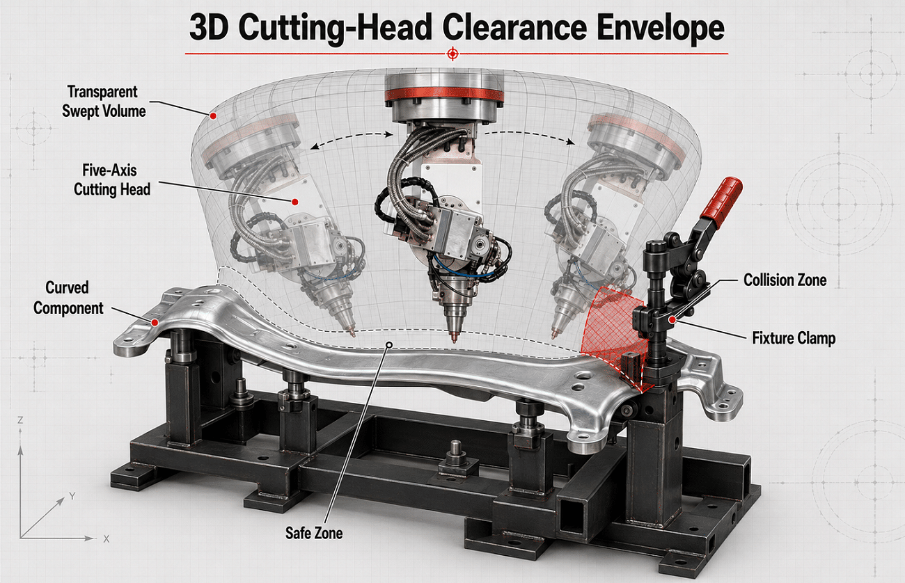
The fixture must therefore provide a 3D access envelope, not only clearance around the laser beam.
Consider the Entire Cutting Head
Do not simulate only:
- Laser beam
- Nozzle tip
Include:
- Nozzle
- Cutting-head body
- Rotary head structure
- Protective components
- Cables or fiber routing where relevant
A clamp may be 40 mm away from the trim line and still cause a collision because the upper body of the tilted cutting head passes through that space.
Evaluate Every Cutting Orientation
A clear path at 0° does not mean the fixture is accessible at:
- 30°
- 45°
- 70°
- Other required orientations
ZG Laser’s current five-axis platforms are designed specifically for multi-direction trimming, holes, contours and bevels on formed and irregular workpieces, which makes fixture clearance part of the complete five-axis application rather than a separate issue.
11. Create a Cutting-Head Keep-Out Zone
A useful fixture-design method is to create a keep-out volume around the programmed cutting path.
Instead of asking:
“Is this clamp close to the trim line?”
ask:
“Will any part of the five-axis head occupy this volume during the complete programmed movement?”
The digital model should include:
- Head geometry
- Nozzle
- Required tilt angles
- Lead-in movement
- Lead-out movement
- Rapid approach
- Retract movement
Fixture components should remain outside this envelope wherever possible.
Critical Areas
Pay particular attention near:
- Recessed holes
- Deep walls
- Corners
- End trims
- Tight radii
- Close-proximity clamps
12. Fixture Design and Programming Should Happen Together
Do not complete the fixture first and only then ask the programmer to make the laser path fit.
That workflow often creates unnecessary compromises.
A better process is iterative:
Part CAD
→ Preliminary Cutting Path
→ Fixture Concept
→ Head Accessibility Simulation
→ Fixture Revision
→ Final Path
→ Collision Validation
Example
Suppose a clamp blocks access to an assembly hole.
Possible solutions include:
- Move the clamp
- Change clamp geometry
- Change head orientation
- Change cutting sequence
- Temporarily release the clamp
- Use a different locating strategy
The best solution cannot be determined by the fixture designer or programmer independently.
This is why fixture design and offline programming should be treated as one engineering process.
13. Include the Complete Fixture in Collision Simulation
The digital simulation model should contain more than the workpiece.
Include:
- Fixture base
- Locating pins
- Supports
- Clamps
- Pneumatic cylinders
- Sensors
- Hose brackets
- Worktable
- Rotary table
- Cutting head
- Machine envelope
The earlier the fixture exists as a proper 3D model, the easier it is to detect interference before manufacturing.
Do Not Simplify Critical Geometry Too Much
A programmer may model a clamp only as a small rectangular block.
The real clamp may include:
- Lever arm
- Cylinder
- Fasteners
- Bracket
- Hose fitting
One of these can become the real collision point.
For five-axis processing, the simulation model should represent the geometry that actually occupies space.
14. Design for Nozzle-to-Part Distance
The nozzle must maintain the appropriate relationship with the workpiece surface.
Fixture design can interfere with this when:
- Supports are too close to a cut
- Clamps obstruct head approach
- The part cannot be seated correctly
- The surface is pushed away from nominal position
The fixture should maintain the workpiece in a predictable location so the height-control system operates within its intended range.
This becomes more challenging around:
- Steep surfaces
- Deep recesses
- Sharp transitions
- Small radii
Accessibility should therefore be evaluated at the nozzle and cutting-head level—not only by checking whether the laser beam theoretically reaches the contour.
15. Provide Clearance for Slag and Molten Material
The laser removes material from the cutting kerf.
That material must go somewhere.
Fixture designers should consider the direction of:
- Molten metal
- Sparks
- Slugs
- Smoke
- Dust
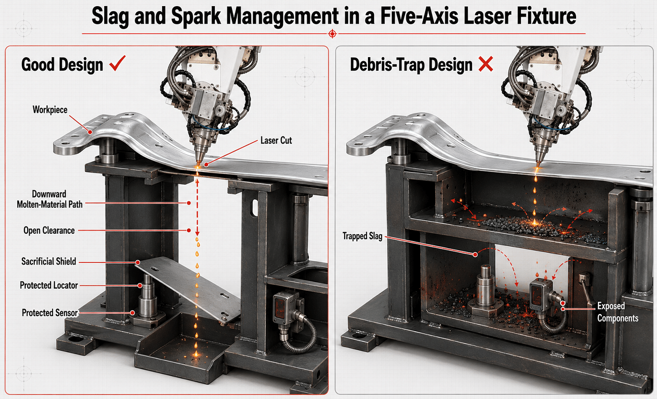
Avoid Placing Precision Elements Directly Below Cuts
Do not position critical:
- Locating pads
- Linear guides
- Sensors
- Pneumatic seals
- Cables
directly in the expected slag path where practical.
Repeated exposure can lead to:
- Slag buildup
- Sensor failure
- Locator contamination
- Damaged hoses
- Changed fixture height
Provide Open Areas Below Trim Lines
Where possible, allow:
- Molten material to fall away
- Slugs to leave the fixture
- Fumes to reach extraction zones
Do not create closed pockets that gradually fill with cutting debris.
16. Use Sacrificial Protection in High-Exposure Areas
Some fixture areas cannot avoid exposure.
Instead of allowing expensive structural components to absorb repeated sparks and slag, add replaceable protection.
Possible components include:
- Sacrificial plates
- Heat shields
- Replaceable strips
- Protective covers
Design these components so that they can be:
- Replaced quickly
- Installed repeatably
- Inspected easily
A sacrificial part should not become an uncontrolled datum as it wears.
Keep precision locating elements functionally separate from expendable protective components where possible.
17. Cutting Sequence Can Change How the Part Sits
A formed component may contain residual stress.
As material is trimmed away, its stiffness and stress distribution can change.
Possible effects include:
- Edge movement
- Flange relaxation
- Local springback
- Scrap hanging from the component
Therefore, fixture design cannot always be separated from cutting sequence.
Example
If a large perimeter trim is completed first, the part may lose support before several critical holes are cut.
An alternative sequence may be:
- Locate and clamp.
- Cut critical holes.
- Cut internal slots.
- Complete selected trim features.
- Finish the external contour.
The best sequence depends on the component.
Fixture Support After Trimming
Ask:
After this section is removed, what still supports the remaining component?
A support located under scrap rather than the finished component may disappear functionally halfway through the cycle.
18. Design for Incoming Part Variation
Real formed parts vary.
The fixture needs to accommodate the expected process variation without introducing inconsistent positioning.
Possible variation includes:
- Springback
- Flange height
- Local curvature
- Hole position
- Overall twist
- Weld distortion
Do Not Locate From Highly Variable Areas
If possible, select the most stable manufacturing features as references.
Adjustable Supports
May be useful when:
- Surface height varies
- Castings have irregular contact areas
- Large parts require additional support
Carr Lane identifies adjustable and equalizing supports as methods for accommodating workpiece surfaces where fixed supports are unsuitable.
Sensing
For applications with meaningful variation, the cell may also use:
- Probes
- Part-presence sensors
- Vision
- Datum detection
Renishaw describes part setting as establishing the position of datum features and work coordinate systems before machining; the same general manufacturing principle is useful when evaluating whether a variable incoming 3D part requires automated positional verification.
Whether this is necessary depends on:
- Incoming variation
- Required tolerance
- Production volume
- Machine capabilities
19. Do Not Expect Sensing to Fix a Bad Fixture
Part sensing is useful.
But it should not be used as an excuse for unstable workholding.
A sensing system can potentially identify:
- Part position
- Orientation
- Datum location
It cannot necessarily correct:
- A flexible component that rocks
- Random clamping deformation
- Loose locating pins
- Fixture wear
- Unpredictable springback
Use sensing to measure controlled variation.
Do not use it to compensate for an uncontrolled fixture.
20. Fixed-Table and Rotary-Table Fixtures Have Different Requirements
Fixture design also depends on machine architecture.
Fixed Table
A fixed-table fixture may suit:
- Large components
- Prototype production
- Low-to-medium volume
- Flexible part changes
Priorities include:
- Operator access
- Fixture changeover
- Maximum head accessibility
Rotary or Exchange Table
A rotary-table system can support:
- Alternating loading and cutting
- Two production stations
- Higher-volume production
- Robotic loading
But the fixture must also withstand:
- Table acceleration
- Rotation
- Repeated indexing
The fixture and component must remain stable during movement.
ZG Laser’s current five-axis portfolio includes platforms intended for both flexible processing and higher-cycle automotive production, so fixture concepts should follow the production architecture rather than use one universal design.
21. Design for Manual Loading From the Beginning
If operators will load the component manually, fixture ergonomics affect productivity.
Consider:
- Part weight
- Loading direction
- Reach distance
- Sharp edges
- Correct orientation
- Clamp sequence
- Operator visibility
Make Incorrect Loading Difficult
A fixture can include mistake-proofing features so the component:
- Cannot be loaded backward
- Cannot be rotated incorrectly
- Cannot be clamped before fully seated
Carr Lane describes foolproofing as an important fixture-design principle and notes that strategically placed locating features can prevent incorrect orientation.
Typical Methods
- Asymmetric locating pins
- Mechanical stops
- Part-presence sensors
- Clamp-position sensors
- Visual reference features
Reducing loading errors is often more valuable than reducing theoretical loading time by one or two seconds.
22. Robot Loading Changes the Fixture Design
If a robot will load the part, fixture access must work for both:
the laser cutting head
and
the handling robot or gripper.
The fixture must consider:
- Robot approach direction
- Gripper clearance
- Part release
- Clamp opening
- Sensor position
- Robot withdrawal path
A clamp placement that is ideal for manual loading may block the robot gripper.
Therefore, automated fixtures should be developed together with:
- Robot reach study
- Gripper design
- Laser-head simulation
23. Pneumatic vs Manual Clamping
Manual Clamps
May be suitable for:
- Prototype production
- Low volumes
- Frequent fixture changes
- Simple components
Benefits include:
- Lower cost
- Simple maintenance
- Easy adjustment
But the result may depend more on operator technique.
Pneumatic Clamps
Can support:
- Shorter loading cycles
- Consistent actuation
- Automation
- Sensor feedback
Important considerations include:
- Clamp force
- Pressure stability
- Fail-safe behavior
- Hose routing
- Protection from slag
Hydraulic Clamping
May be appropriate for selected heavy fixtures but often adds complexity unnecessary for lightweight sheet-metal laser trimming.
Choose the actuation system according to the real holding requirement—not simply because more force is available.
24. Quick-Change Fixture Design for Multiple Parts
One advantage of five-axis laser cutting is product flexibility.
That advantage can disappear if changing fixtures takes hours.
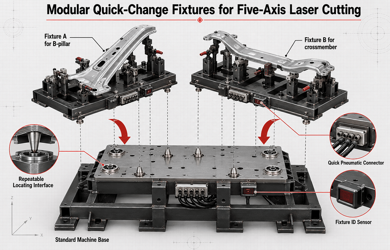
For multiple product variants, consider standardized:
- Fixture bases
- Zero-point references
- Locating interfaces
- Pneumatic connectors
- Electrical connectors
- Fixture identification
A Quick-Change Fixture Should Repeat Its Position
Fast changeover has little value if every change requires lengthy re-teaching.
The fixture should return to a known relationship with the machine coordinate system.
Depending on production requirements, changeover may include:
- Mechanical repeatable locating
- Fixture verification
- Probe check
- Stored coordinate offsets
25. Fixture Materials and Construction
Fixture construction should balance:
- Rigidity
- Weight
- Heat resistance
- Manufacturability
- Cost
- Maintainability
Possible materials include:
- Structural steel
- Tool steel for locating components
- Aluminum for selected lightweight structures
- Engineered replaceable contact components
Precision Components
Locating pins and datum elements may require:
- Higher hardness
- Controlled tolerance
- Wear resistance
- Replaceability
Structural Components
Fixture frames should remain stable under:
- Part loading
- Clamp force
- Table movement
But unnecessary mass can make:
- Fixture changes difficult
- Rotary-table dynamics worse
- Maintenance harder
Design only the stiffness the application requires.
26. Fixture Repeatability Should Be Measured
Do not assume that a well-machined fixture is repeatable.
Test it.
A practical fixture validation can include:
- Load the same component.
- Clamp it.
- Measure selected datum or feature positions.
- Unload the component.
- Repeat the loading cycle.
- Compare results.
This helps separate:
fixture loading variation
from:
machine cutting variation.
Use More Than One Production Part
After the fixture itself is evaluated, load several real parts.
This helps identify the difference between:
- Fixture repeatability
- Incoming-part variation
If one part repeats well but different parts do not, the incoming geometry may be the dominant issue.
27. Do Not Specify Extreme Precision Everywhere
Fixture tolerances should support the finished-part requirement.
Not every fixture component needs ultra-tight tolerances.
Critical elements include:
- Locator positions
- Datum pads
- Fixture-to-machine interfaces
Less critical elements may include:
- Protective covers
- Non-datum structural members
- Slag shields
Over-specifying the entire fixture increases:
- Machining cost
- Inspection cost
- Lead time
without necessarily improving final accuracy.
The tolerance strategy should follow the actual dimensional chain.
28. Design the Fixture for Inspection and Maintenance
Production fixtures change over time.
Common issues include:
- Worn locating pins
- Damaged supports
- Slag buildup
- Loose fasteners
- Clamp wear
- Sensor damage
A good fixture should make these areas easy to:
- Inspect
- Clean
- Replace
- Recalibrate
Replaceable Wear Components
Consider replaceable:
- Locating pins
- Rest pads
- Protective shields
Rather than rebuilding the complete fixture after wear.
Provide Cleaning Access
Avoid deep pockets where:
- Slag
- Dust
- Scrap
can accumulate unnoticed.
A small piece of debris on a datum pad can shift the entire component.
29. Establish a Fixture Maintenance Standard
For production applications, fixture maintenance should not depend on an operator noticing a problem.
Define checks such as:
Every Shift or Daily
- Datum cleanliness
- Clamp condition
- Part-presence sensors
- Slag buildup
Periodically
- Locator wear
- Clamp force
- Pneumatic leakage
- Fixture mounting
- Dimensional reference checks
After a Collision
Inspect:
- Fixture position
- Damaged clamp
- Locator
- Cutting-head calibration
The interval should depend on:
- Production volume
- Fixture design
- Material
- Exposure to slag
30. Common Fixture Design Problems
| Problem | Likely Cause | Improvement Direction |
|---|---|---|
| Part loads differently each cycle | Unclear datum or unstable locator | Review locating strategy |
| Part rocks in fixture | Insufficient or poorly placed supports | Improve support layout |
| Part distorts when clamped | Excessive force or unsupported clamp area | Reduce force and support near clamp |
| Laser head hits clamp | Fixture designed without full head envelope | Simulate complete 5-axis motion |
| Hole position varies between parts | Incoming-part variation or locating inconsistency | Measure incoming parts and datums |
| Good while clamped, bad after release | Fixture forcing component into shape | Reduce over-constraint |
| Slag builds on locator | Locator placed in cutting path | Add shield or relocate locator |
| Sensors fail frequently | Direct spark/slag exposure | Protect or reposition sensor |
| Long fixture changeover | No standardized base/interface | Use modular quick-change concept |
| Wrong part loaded | No foolproofing | Add asymmetric locator or detection |
| Program works on one fixture but not another | Fixture-to-machine reference variation | Improve repeatable fixture mounting |
| Finish changes after several hundred parts | Wear or contamination | Establish maintenance checks |
31. A Practical Fixture Design Workflow
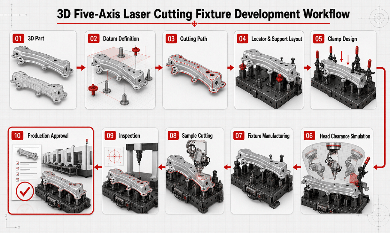
A structured fixture-development process can follow these stages.
Step 1 — Review the Part
Collect:
- 3D CAD
- Drawing
- Material
- Thickness
- Part variation
- Critical features
Step 2 — Define Functional Datums
Identify:
- Primary datum
- Secondary datum
- Tertiary datum
Step 3 — Develop the Cutting Path Concept
Determine:
- Trim lines
- Holes
- Slots
- Cutting-head angles
Step 4 — Select Locating Points
Choose stable features that support the dimensional requirements.
Step 5 — Add Supports
Control:
- Sag
- Vibration
- Flexible sections
without unnecessarily over-constraining the component.
Step 6 — Add Clamps
Clamp toward locators using the minimum effective force.
Step 7 — Create the Head Clearance Envelope
Simulate all required orientations.
Step 8 — Design Slag Clearance
Protect:
- Locators
- Sensors
- Pneumatics
Step 9 — Review Loading
Evaluate:
- Manual or robotic access
- Error-proofing
- Clamp sequence
Step 10 — Build the Digital Fixture Model
Include all collision-relevant geometry.
Step 11 — Simulate the Complete Program
Check:
- Cutting
- Rapid movement
- Table rotation
- Loading where relevant
Step 12 — Build and Inspect the Fixture
Verify critical fixture datums.
Step 13 — Run Sample Parts
Measure:
- Repeat loading
- Critical cut dimensions
- Part deformation
Step 14 — Revise
Fixture development should include allowance for adjustment after real sample testing.
32. How Should a Fixture Be Validated?
Fixture validation should answer four separate questions.
1. Does the Part Load Correctly?
Check:
- Orientation
- Full seating
- Locator engagement
- Clamp sequence
2. Is Loading Repeatable?
Repeat the loading operation several times.
Measure reference positions.
3. Is the Part Being Distorted?
Compare:
- Free-state geometry
- Clamped geometry
- Geometry after cutting and release
4. Is the Cutting Head Fully Accessible?
Run:
- Simulation
- Reduced-speed verification
- Controlled first sample
The fixture should pass all four before production approval.
33. Sample Cutting Is Part of Fixture Development
A fixture should not be considered finished simply because it matches CAD.
The real validation happens with:
- Actual production part
- Actual machine
- Actual laser head
- Actual cutting program
Record During Testing
Fixture
- Datum configuration
- Clamp pressure
- Loading sequence
Machine
- Machine model
- Head configuration
- Calibration condition
Cutting
- Path
- Gas
- Focus
- Speed
Inspection
- Critical dimensions
- Measurement datum
- Repeatability
Run Several Parts
One part may prove that the fixture physically works.
Repeated parts begin to show whether the fixture is stable enough for production.
34. Fixture Design for Hot-Formed Automotive Parts
Hot-formed automotive components are one of the most important applications for dedicated five-axis laser trimming.
Typical parts include:
- B-pillars
- Door rings
- Crossmembers
- Roof rails
- Rocker reinforcements
- Bumper structures
These parts create several fixture challenges:
- Large 3D geometry
- Thin but high-strength sections
- Multiple trimming surfaces
- Deep side-wall holes
- Forming variation
- High-volume cycle requirements
The fixture should therefore balance:
accuracy + access + cycle time
rather than optimize any one factor independently.
For repetitive automotive production, the fixture may also include:
- Pneumatic clamps
- Part-presence sensors
- Rotary-table interface
- Automated loading features
35. Fixture Design for Five-Axis Machine vs Robot Cell
A dedicated five-axis machine and robotic laser cutting cell may require different fixture layouts.
Dedicated Five-Axis Machine
The fixture must fit within:
- Defined machine workspace
- Table dimensions
- Rotary-head movement
This makes the working envelope relatively predictable.
Robot Cell
A robot fixture may be installed:
- Around the robot
- On an external positioner
- On a rotary table
- Across multiple stations
This offers more layout freedom but introduces:
- Robot-arm clearance
- Elbow clearance
- Wrist clearance
- Positioner movement
Both architectures still depend on consistent locating.
36. What Information Should the Customer Provide?
Fixture design becomes much more efficient when the customer supplies complete engineering data.
Provide:
- 3D CAD model
- 2D drawing
- Material
- Thickness
- Forming process
- Incoming part tolerances
- Critical dimensions
- Functional datums
- Trim contours
- Holes and slots
- Annual production volume
- Parts per shift
- Target cycle time
- Manual or robotic loading
- Inspection method
- Existing checking fixture information
- Expected product variants
Also Provide Physical Samples
For formed parts, physical production samples are extremely valuable.
The nominal CAD model cannot always reveal:
- Real springback
- Surface variation
- Flange variation
- Loading behavior
Fixture engineering should therefore use both:
nominal CAD
and
representative real parts.
37. Questions to Ask a Fixture or Machine Supplier
Before approving a project, ask:
- Which features will be used as datums?
- Why were those datums selected?
- Which points are locators and which are only supports?
- How is redundant location avoided?
- How is incoming-part variation accommodated?
- How much clamp force is required?
- Can the clamps deform the component?
- Is the complete laser-head envelope simulated?
- Are clamps clear at every cutting-head angle?
- How is slag kept away from locators?
- Are wear components replaceable?
- How is fixture repeatability verified?
- How is the fixture referenced to the machine?
- Can the fixture support multiple variants?
- How long does fixture changeover take?
- Is manual loading mistake-proofed?
- Is robotic loading required?
- Are sensors protected from cutting debris?
- What maintenance is required?
- Will repeated sample parts be measured?
A good fixture proposal should explain the location strategy, not simply show an attractive 3D rendering.
38. Final Fixture Design Checklist
Before approving a fixture, confirm:
- Functional datums identified
- Stable locating features selected
- Primary / secondary / tertiary logic defined
- Redundant location avoided
- Flexible areas adequately supported
- Clamp force minimized
- Clamps act toward locators
- Clamp-induced deformation evaluated
- Complete five-axis head envelope simulated
- Deep and angled features accessible
- Rapid movements checked
- Slag clearance provided
- Precision locators protected
- Sensors protected
- Scrap removal considered
- Cutting sequence reviewed
- Part variation evaluated
- Manual or robotic loading verified
- Incorrect loading prevented
- Fixture-to-machine reference repeatable
- Quick-change requirement evaluated
- Wear parts replaceable
- Cleaning access provided
- Maintenance method defined
- Repeat-loading test completed
- Actual sample parts cut
- Finished-part inspection completed
Conclusion
Fixture design is not a secondary detail in 3D five-axis laser cutting.
It is part of the cutting system.
The machine can only apply the programmed path accurately when the workpiece occupies a known and repeatable position.
A successful fixture therefore requires more than simply holding the component tightly.
It must:
- Establish meaningful datums
- Locate the part consistently
- Support flexible areas
- Avoid excessive clamping
- Accommodate normal part variation
- Leave complete five-axis head access
- Manage slag and cutting debris
- Support efficient loading
- Maintain repeatability during production
The most important principle is:
The fixture should locate the part—not force the part into shape.
And for five-axis processing:
Every clamp, locator and support must be evaluated not only against the part, but against the complete movement envelope of the cutting head.
For this reason, the best fixture-development process combines:
part engineering + fixture design + offline programming + collision simulation + sample cutting + dimensional inspection
before production begins.
Evaluate the Fixture Together With the Five-Axis Cutting Process
Send ZG Laser:
- Your 3D part model
- 2D drawing
- Material and thickness
- Critical datums
- Required trim paths
- Tolerances
- Annual volume
- Target cycle time
- Loading requirements
Our application team can evaluate:
- Part locating strategy
- Fixture concept
- Cutting-head accessibility
- Worktable configuration
- Five-axis cutting path
- Sample validation requirements
before the final machine and fixture configuration is confirmed.
What Determines 3D Five-Axis Laser Cutting Accuracy?
Frequently Asked Questions
Why is fixture design important in five-axis laser cutting?
The fixture establishes the workpiece position relative to the machine. If the part is positioned differently between cycles, the laser follows the same programmed path on a differently located component.
What is the 3-2-1 principle in fixture design?
The classical 3-2-1 principle uses three primary, two secondary and one tertiary locating contacts to establish a workpiece position and orientation. Additional supports may be required for large or flexible formed parts.
Should a laser cutting fixture clamp the part tightly?
It should clamp securely, but excessive force can deform thin or formed parts. Laser cutting is non-contact, so the fixture normally needs enough force to maintain reliable locating rather than the high forces associated with heavy machining.
Can too many locating points reduce accuracy?
Yes. Redundant locating points can create competing contacts when real parts vary, leading to inconsistent seating.
Should clamps be placed close to the laser cutting path?
Only when complete cutting-head clearance has been verified. A clamp can be clear of the laser beam but still collide with the body of a tilted five-axis cutting head.
How do you prevent fixture deformation of thin parts?
Use stable locating points, sufficient support and the minimum effective clamping force. Place clamps near supported areas and avoid using force to push the component into nominal CAD geometry.
How should a fixture accommodate hot-formed part variation?
Use stable production datums and separate locating functions from additional support. Depending on the application, adjustable supports or part sensing may also be evaluated.
Should the fixture be included in offline programming?
Yes. The digital model should contain clamps, locators, supports, fixture structure and other collision-relevant elements so the complete five-axis head movement can be simulated.
How can slag damage a fixture?
Molten material and debris can accumulate on locators, damage sensors and alter seating surfaces. Fixtures should provide open clearance and sacrificial protection around high-exposure areas.
How do you test fixture repeatability?
Repeatedly load and clamp the same component, measure reference positions, unload it and repeat the process. Then compare multiple production parts to distinguish fixture variation from incoming-part variation.
Do five-axis laser fixtures need maintenance?
Yes. Locators can wear, slag can accumulate, clamps can change and sensors can become damaged. Production fixtures should have scheduled cleaning and inspection.
Should the fixture be finished before laser programming begins?
No. Fixture and cutting-path development should be iterative because clamp position, support geometry and cutting-head orientation directly affect one another.