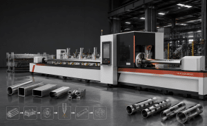
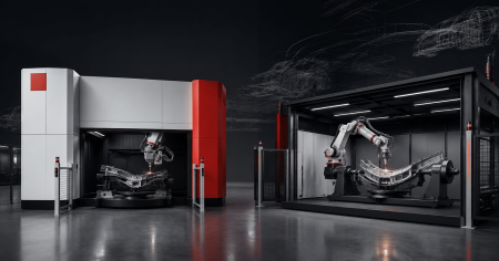
When a metal component cannot be processed on a conventional flatbed laser cutter, manufacturers often face two possible solutions:
- A dedicated 3D five-axis laser cutting machine
- A robotic laser cutting system
Both can move the laser cutting head around complex three-dimensional parts.
Both can process curved surfaces, formed components, holes, contours and multi-angle features.
And both can be integrated into automated manufacturing cells.
However, they achieve this motion in fundamentally different ways.
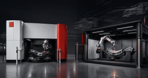
A five-axis laser machine uses a machine-tool-style motion platform with coordinated linear and rotary axes. A robotic system typically uses a six-axis articulated industrial robot carrying the laser cutting head.
That difference influences:
- Working envelope
- Path accuracy
- Repeatability
- Accessibility
- Cycle time
- Programming
- Fixture design
- Factory layout
- Automation
- Investment cost
There is therefore no universal answer to the question:
“Is a five-axis laser cutter better than a robot?”
The correct question is:
Which motion platform is better suited to the geometry, tolerance, volume and production strategy of my parts?
Dedicated five-axis systems are widely used for formed automotive components and other repeatable 3D cutting applications, while industrial robots provide a highly flexible multi-axis platform for laser cutting, welding and other processes. TRUMPF, KUKA and FANUC all currently offer or support 3D laser processing through these different machine architectures.
1. What Is a Five-Axis Laser Cutting Machine?
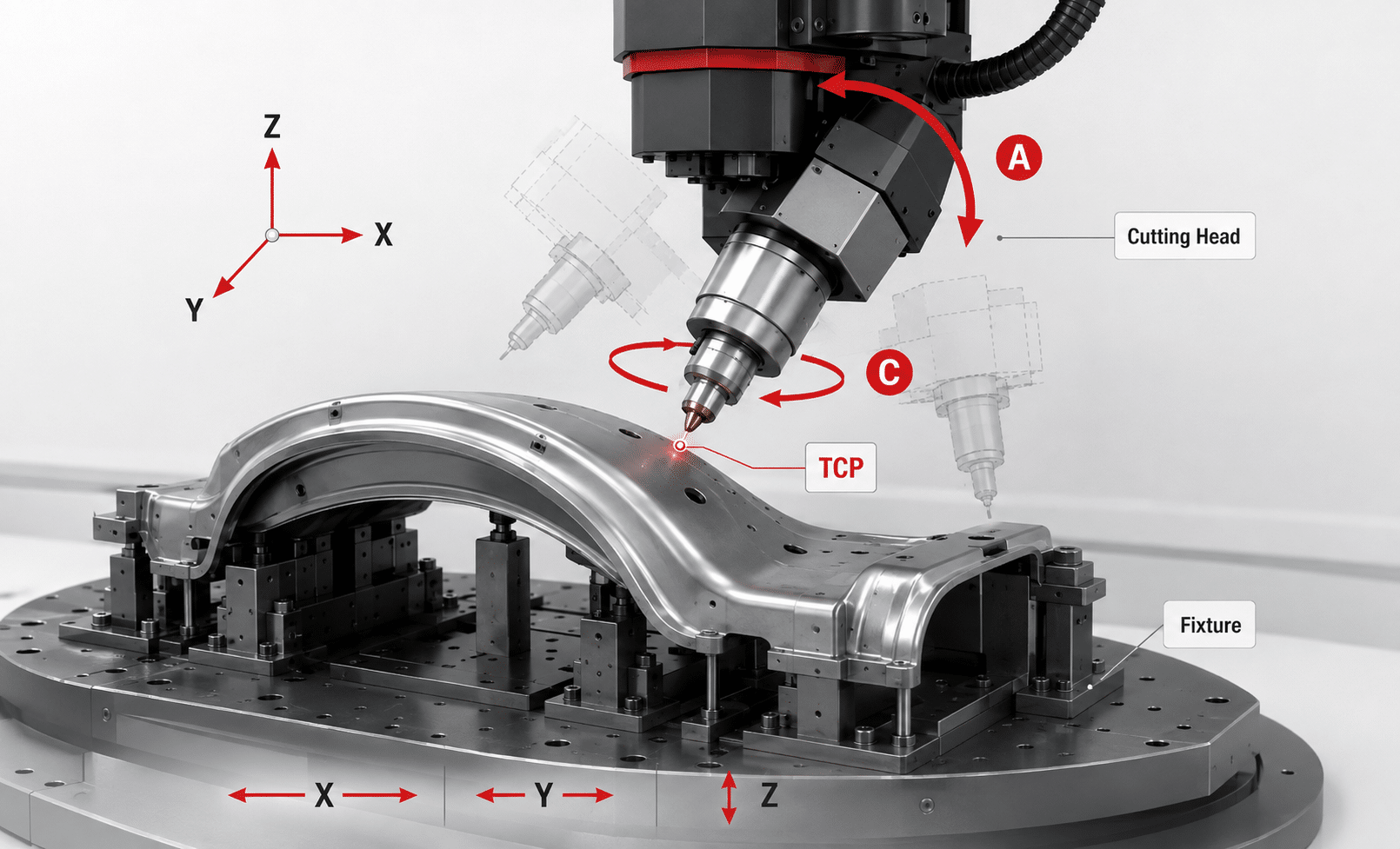
A dedicated five-axis laser cutting machine is designed specifically for processing three-dimensional workpieces.
Instead of moving only over a flat X-Y plane, it coordinates several motion axes so that the cutting head can approach the workpiece from different directions.
A typical configuration includes:
- X-axis
- Y-axis
- Z-axis
- One rotary axis
- A second rotary axis
The exact axis naming and mechanical arrangement varies between manufacturers.
The purpose is the same:
control both the position and orientation of the laser cutting head relative to the 3D workpiece.
This allows the system to perform:
- Edge trimming
- Hole cutting
- Slots
- Contour cutting
- Angled cutting
- Bevel features
- Processing around curved surfaces
ZG Laser’s five-axis range is currently positioned for formed, curved and irregular metal parts and supports trimming, hole cutting, bevel cutting and multi-angle contour processing.
Typical Five-Axis Applications
Typical parts include:
- Automotive B-pillars
- Door rings
- Crossmembers
- Rocker reinforcements
- Hydroformed tubes
- Stamped panels
- Curved housings
- Aerospace components
- Complex formed metal parts
Dedicated hot-forming laser machines from established manufacturers such as TRUMPF are similarly designed around parts including B-pillars and crossmembers.
2. What Is a Robotic Laser Cutting System?
A robotic laser cutting system normally uses a multi-joint industrial robot to position the cutting head.
A typical industrial robot has six axes of motion.
Instead of moving along the linear guideways of a conventional machine tool, the robot combines several rotating joints:
- Base rotation
- Shoulder
- Elbow
- Wrist axes
The resulting motion allows the robot to reach around complex parts from many orientations.
ZG Laser currently describes its robotic cutting system as a six-axis platform for multi-dimensional and multi-angle 3D metal cutting, including curved parts, tubes and automotive components.
Industrial robot manufacturers also specifically support 3D laser cutting. KUKA positions robots for spatial 3D laser cutting, while FANUC offers six-axis robots designed for precision laser cutting and welding applications.
A Robot Cell May Also Include
- Laser source
- Cutting head
- Industrial robot
- Fixture
- Positioner
- Linear track
- Safety enclosure
- Extraction system
- Offline programming software
- Vision system
- Loading robot
This makes robotic laser cutting highly configurable.
3. Five-Axis vs Robotic Laser Cutting: Quick Comparison
| Factor | Dedicated Five-Axis Machine | Robotic Laser Cutting |
|---|---|---|
| Motion structure | Machine-tool linear + rotary axes | Articulated multi-joint robot |
| Typical axes | 5 coordinated axes | Usually 6 robot axes |
| Working envelope | Defined machine workspace | Flexible robot reach |
| Large-part flexibility | Depends on machine travel | Strong advantage with robot reach or track |
| Path behavior | Machine-specific controlled kinematics | Depends strongly on robot posture and calibration |
| Repetitive production | Strong fit | Also possible with proper cell design |
| Part variety | Flexible with programs and fixtures | Highly flexible |
| Fixture | Normally dedicated fixture | Fixture or positioner |
| Programming | 3D CAM / machine CNC | Robot offline programming / simulation |
| Collision simulation | Important | Critical |
| Rotary table | Common option | Positioners can be integrated |
| Floor space | Defined enclosed machine footprint | Cell size varies significantly |
| Automation | Rotary tables, loaders, robots | Highly configurable |
| Typical strength | Controlled 3D production | Reach and flexibility |
| Typical applications | Hot-formed parts, formed components | Varied, large or complex 3D parts |
This table is a starting point rather than a universal performance ranking.
Robot design, five-axis machine architecture, software, calibration and application requirements can significantly change the result.
4. The Biggest Difference: Motion Architecture
The most important difference between the two technologies is not the laser.
It is the machine motion.
Five-Axis Machine
A five-axis machine typically uses:
- Precision linear guideways
- Servo-driven machine axes
- Defined rotary-axis geometry
- Rigid machine structure
- CNC interpolation
The motion system is designed around a specific working volume.
Once the workpiece is located in the machine coordinate system, the CNC coordinates all axes to keep the cutting tool at the programmed position and orientation.
Industrial Robot
An articulated robot uses a chain of rotary joints.
The final cutting-head position depends on the combined angular position of every joint in the chain.
This provides extremely flexible movement but introduces another important consideration:
robot posture.
The same cutting point may sometimes be reachable through several robot configurations.
Different postures can affect:
- Rigidity
- Speed
- Accessibility
- Path behavior
- Joint limits
- Cable routing
- Collision risk
For this reason, robotic laser cutting requires careful path planning and simulation.
5. Which Is More Accurate?
This is one of the most common—and most oversimplified—questions.
The traditional answer is often:
Five-axis machine = precise
Robot = flexible but inaccurate
That statement is no longer sufficient.
Modern industrial robots designed specifically for high-precision path applications have significantly improved.
For example, FANUC’s current M-800/60-20B is explicitly intended for applications including 3D laser cutting. FANUC publishes ±0.1 mm circular and linear path accuracy and ±0.015 mm repeatability for this specific high-precision robot configuration.
This does not mean every industrial robot achieves these figures.
It means robot selection and calibration matter.
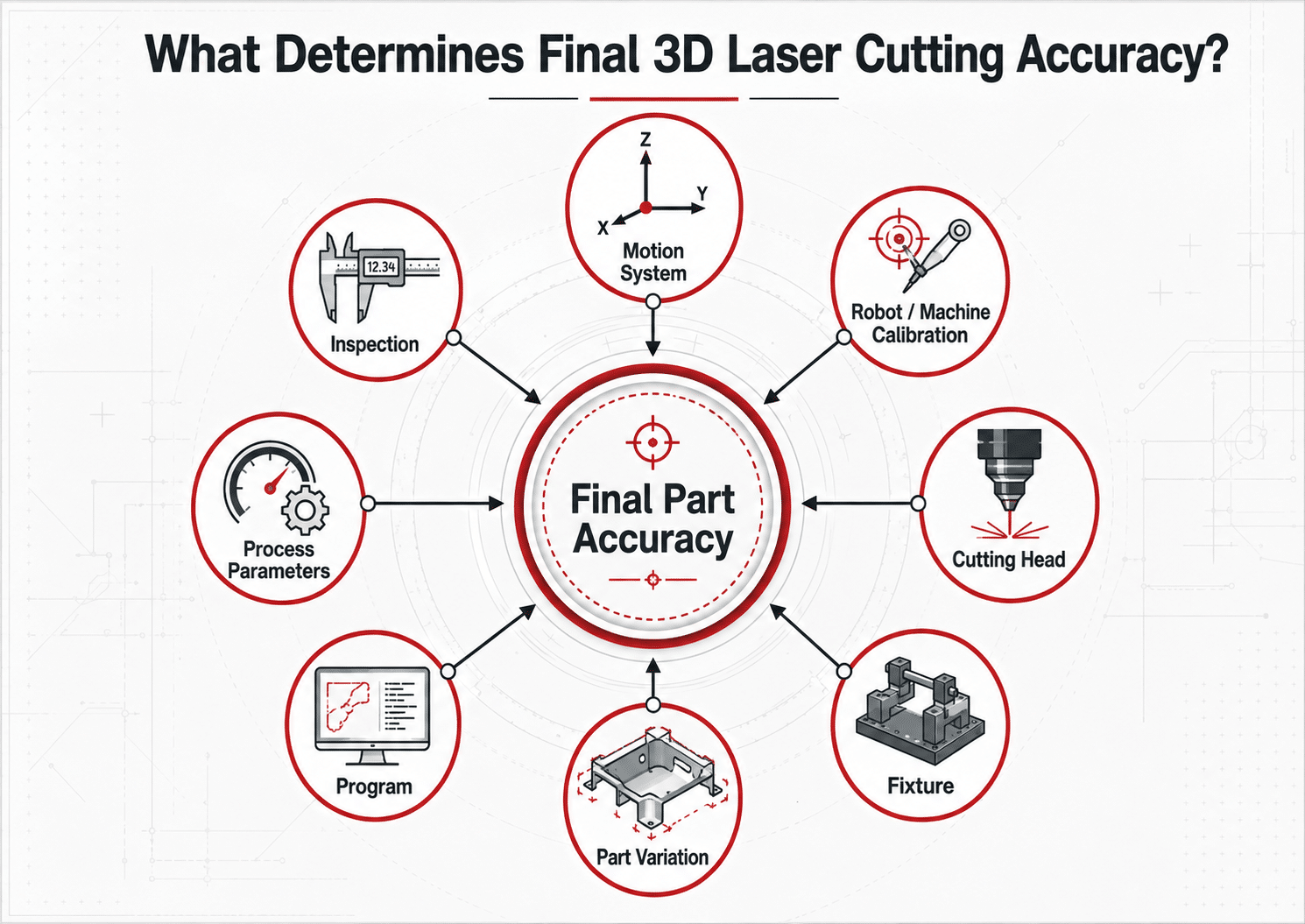
Five-Axis Accuracy Depends On
- Linear-axis accuracy
- Rotary-axis accuracy
- Machine rigidity
- Tool-center-point calibration
- Cutting-head calibration
- Fixture repeatability
- Thermal stability
Robot Accuracy Depends On
- Robot model
- Absolute positioning accuracy
- Repeatability
- Joint backlash
- Structural deflection
- Calibration
- Robot posture
- Tool-center-point calibration
- Fixture location
Part Accuracy Depends On Even More
Final cutting accuracy also includes:
- Formed-part variation
- Fixture variation
- Cutting parameters
- Kerf compensation
- Material behavior
- Measurement method
Therefore, do not compare:
machine specification vs robot specification
and assume that determines final part tolerance.
Compare:
actual finished parts produced under representative conditions.
6. Which Has the Larger Working Range?
Robots generally provide an attractive solution when a large and flexible reach is required.
An industrial robot can be installed:
- On the floor
- On a pedestal
- Overhead
- On a linear rail
The workpiece can also be mounted on a:
- Rotary positioner
- Tilt-rotate positioner
- Turntable
This can create a very large effective working envelope.
KUKA specifically emphasizes the flexibility of robotic cutting systems for different production requirements, while industrial robots can also be combined with external axes to extend the effective workspace.
Five-Axis Machine Working Range
A five-axis machine has a defined X/Y/Z travel and rotary-axis range.
This provides predictable working geometry but creates a clear maximum envelope.
The machine must be selected according to:
- Maximum component dimensions
- Fixture dimensions
- Required cutting orientations
- Head clearance
- Loading method
ZG Laser therefore offers several five-axis platforms with different working ranges and configurations rather than one universal machine size.
Robot Advantage
Robots deserve strong consideration when:
- Parts are very large
- The required reach changes significantly
- Several fixtures surround the robot
- A linear track can be used
- Multiple stations must be serviced
7. Which Is Better for Hot-Formed Automotive Parts?
For repetitive trimming of press-hardened automotive components, a dedicated five-axis platform is a particularly established solution.
Typical applications include:
- B-pillars
- Door rings
- Crossmembers
- Roof reinforcements
- Structural panels
TRUMPF’s dedicated hot-forming machines are designed specifically for this production environment, including B-pillars and high-volume hot-formed crossmembers. Rotary tables are also used to reduce non-productive loading time.
ZG Laser’s S-Auto platform is similarly positioned specifically around automotive hot-formed structural parts and high-cycle production.
Why a Dedicated Machine Can Be Attractive
The production environment is predictable:
- Repeated part family
- Dedicated fixtures
- Defined working envelope
- Stable cutting sequence
- High utilization
- Repeatable loading strategy
This allows the entire machine to be optimized around one type of production.
Does This Mean Robots Cannot Cut Automotive Parts?
No.
Robots are widely used in automotive manufacturing and can perform 3D laser cutting.
KUKA documents automotive laser cutting of complex 3D geometries in production cells, while FANUC specifically targets new high-precision robots at automotive applications including large cast structures.
The choice depends on the component.
Laser trimming of hot-formed automotive parts
8. Which Is Better for Large 3D Parts?
A robot can become particularly attractive as part size increases.
Consider components such as:
- Large castings
- Vehicle structures
- Construction-machinery parts
- Large fabricated assemblies
- Large housings
- Oversized prototypes
Building a dedicated five-axis machine around a very large working envelope may increase:
- Machine footprint
- Structural requirements
- Investment
- Loading complexity
A robot may instead reach the part from several directions or move along an additional linear axis.
FANUC specifically identifies large automotive gigacastings as an example where high-precision robotic processing can provide an alternative or complement to traditional large CNC machine tools.
But Reach Is Not the Only Requirement
For large parts, evaluate:
- Required tolerance
- Fixture accuracy
- Robot posture
- Cutting-head accessibility
- Calibration
- Structural rigidity
- Thermal effects
- Cycle time
A large reachable envelope is useful only if the process performs adequately across that envelope.
9. Which Is More Flexible for Product Changes?
Both technologies are digitally programmable, so both are substantially more flexible than dedicated mechanical trimming tooling.
However, robotic cells provide particularly strong mechanical flexibility.
The robot can potentially:
- Move between several fixtures
- Reach different part sizes
- Change approach direction
- Process different product families
- Use external axes
- Support other compatible laser processes
KUKA’s laser application software, for example, integrates cutting and welding functionality directly with robot programming, highlighting the ability of a robot platform to support several laser processes.
Five-Axis Flexibility
A five-axis machine also offers strong product flexibility.
Changing production can involve:
- New fixture
- New 3D model
- New CAM program
- New cutting parameters
TRUMPF highlights NC programming as a way to adapt hot-formed components to changed geometry without developing a new conventional trimming tool.
Practical Difference
Think of it this way:
Five-axis flexibility:
Flexible production inside a defined machine workspace.
Robot flexibility:
Flexible production through a highly adaptable motion platform.
10. Which Has the Better Cycle Time?
There is no universal winner.
Cycle time depends on:
- Part geometry
- Cutting length
- Number of holes
- Piercing
- Rapid positioning
- Robot or axis movement
- Loading
- Fixture clamping
- Table changing
- Unloading
Five-Axis Machine
Dedicated machines can be optimized for repetitive movement.
For series production, features such as:
- Rotary tables
- Multiple stations
- Fast doors
- High machine dynamics
can reduce non-cutting time.
TRUMPF’s current 3D laser cells use rotary-table and multi-station concepts specifically to allow loading and unloading while production continues.
Robot
Robot productivity depends heavily on:
- Path optimization
- Joint posture
- Robot acceleration
- Cutting orientation
- Positioner coordination
- Loading strategy
A robot cell may be extremely fast when the path is optimized—but inefficient if the robot makes unnecessary orientation changes or approaches poor joint configurations.
Measure Complete Cycle Time
Use:
Total Cycle Time = Loading + Clamping + Positioning + Cutting + Repositioning + Unloading
Do not compare only laser-on time.
11. Which Is Easier to Program?
Both systems require specialist programming for complex three-dimensional workpieces.
Five-Axis Programming
A typical workflow includes:
- Import 3D CAD model
- Define trim geometry
- Generate cutting path
- Set cutting-head orientation
- Model fixture
- Simulate machine movement
- Check collisions
- Generate NC program
- Validate at machine
ZG Laser’s current five-axis system configuration includes offline programming and five-axis control for complex 3D geometries.
Robot Programming
A robotic workflow may include:
- Import CAD model
- Model robot cell
- Define robot TCP
- Generate cutting path
- Optimize robot posture
- Check joint limits
- Simulate collisions
- Generate robot program
- Calibrate real cell
- Validate path
Modern robot manufacturers offer dedicated offline simulation platforms for this work. FANUC, for example, supports offline programming and simulation through ROBOGUIDE, while KUKA provides application software specifically for robotic laser cutting and welding.
Robot Programming Adds Another Question
The programmer must consider:
How should the robot itself move?
not only:
Where should the laser cut?
12. Collision Risk
Collision management is critical for both technologies.
Complex 3D parts may contain:
- Deep cavities
- Tall flanges
- Clamps
- Locating pins
- Fixture frames
- Nearby surfaces
Five-Axis Collision Risks
Possible collisions involve:
- Cutting head vs part
- Nozzle vs flange
- Cutting head vs fixture
- Rotary head vs machine enclosure
Robot Collision Risks
Additional risks may involve:
- Robot forearm
- Robot elbow
- Wrist
- Laser cable
- External axes
- Cell equipment
This makes a complete digital model particularly important for robotic processing.
Always Simulate the Entire System
The simulation model should include:
- Workpiece
- Fixture
- Clamps
- Cutting head
- Robot or machine axes
- Worktable
- Positioner
- Enclosure
Do not simulate the laser path alone.
13. Fixture Requirements
Both systems require accurate workholding.
The fixture determines:
- Workpiece position
- Support
- Clamp stability
- Cutting-head access
- Repeatability
Five-Axis Fixture
Typically mounted on:
- Fixed table
- Rotary table
- Dual station
The fixture can be optimized around the defined machine envelope.
Robot Fixture
Can potentially be arranged:
- Around the robot
- On a turntable
- On an external positioner
- Across several workstations
This creates more layout options.
Important Principle
Flexibility in machine movement does not eliminate the need for accurate fixturing.
Even the most accurate motion platform cannot compensate for a part that moves or is located inconsistently.
14. What About Part Variation?
This is particularly important for:
- Hot-formed components
- Castings
- Hydroformed parts
- Welded assemblies
The real component may differ slightly from its nominal CAD model.
Possible causes include:
- Forming variation
- Springback
- Casting variation
- Welding distortion
- Fixture variation
Both machine types may therefore benefit from:
- Part sensing
- Vision
- Probing
- Coordinate correction
- Offline compensation
The exact sensing capability depends on machine configuration and should be confirmed with the supplier.
15. Five-Axis Machine vs Robot for Small Batch Production
Small-batch production changes the economics.
A dedicated automotive production cell designed around one component may be excessive if production involves:
- Many different products
- Small annual quantities
- Frequent engineering changes
- Prototype work
Robots can be attractive because the same motion platform can accommodate several workstations and changing components.
However, compact dedicated five-axis machines are also increasingly targeted at small- and medium-volume 3D production.
TRUMPF positions its TruLaser Cell 5030 for small-to-medium lot sizes and frequent component changes, while ZG Laser currently positions its SF Series around prototypes and small-to-medium batches.
Therefore:
Small batch does not automatically mean robot.
Compare the actual part portfolio.
16. Five-Axis Machine vs Robot for Mass Production
For repetitive mass production, the production cell becomes more important than the motion platform alone.
Evaluate:
- Loading
- Unloading
- Fixture changes
- Number of stations
- Part detection
- Slug removal
- Cycle-time stability
- Maintenance
- Spare parts
Dedicated five-axis hot-forming systems are specifically available for serial automotive production. TRUMPF’s TruLaser Cell 8030, for example, is designed around high-productivity cutting of hot-formed components and large vehicle side structures.
A robotic solution can also be used for mass production when:
- Robot accuracy is sufficient
- Process capability is validated
- Cycle time is competitive
- Cell automation is correctly designed
Neither should be selected from machine architecture alone.
17. What About Automation?
A five-axis machine and a robot are not mutually exclusive.
This is an important point.
A production cell can contain:
- Five-axis laser machine
- Separate loading robot
- Conveyor
- Inspection station
- Automatic fixture
- Part buffer
In this configuration:
the five-axis machine performs precision processing
while
the robot performs material handling.
This can be an excellent solution for repetitive production because each system performs the task it is optimized for.
Likewise, a robotic laser cutting cell may use:
- One cutting robot
- One handling robot
- Positioners
- Conveyor
- Vision system
So the real comparison is often:
machine-cell architecture vs robot-cell architecture
—not simply machine vs robot arm.
18. Factory Footprint
Five-axis machines usually provide a defined integrated footprint.
The enclosure may contain:
- Machine motion system
- Worktable
- Safety system
- Extraction
- Electrical cabinet
This makes factory planning relatively straightforward.
Robot cells can vary significantly.
A robotic cell might contain:
- Robot
- Pedestal
- Linear rail
- Two positioners
- Safety fence
- Laser-safe enclosure
- Extraction
- Loading area
A robot itself may look compact, while the final cell occupies substantial floor area.
Therefore always compare:
complete production-cell footprint
rather than the size of the robot or machine alone.
19. Safety Requirements
Both processes use high-power industrial lasers and require controlled safety systems.
Typical considerations include:
- Laser-safe enclosure
- Safety interlocks
- Access doors
- Emergency stop
- Fume extraction
- Observation systems
- Fire prevention
- Operator training
Robot cells also require control of:
- Robot movement
- Safety zones
- Positioners
- Automatic loading
- Cell access
The final safety design depends on applicable standards, laser class, machine configuration and destination market.
20. Which Costs More?
It is not accurate to state that one architecture is always cheaper.
Five-Axis Investment May Include
- Machine base
- Five-axis motion system
- Laser
- Cutting head
- Control system
- Worktable
- Fixture
- Enclosure
- Extraction
- Software
Robot Cell Investment May Include
- Robot
- Robot controller
- Laser
- Cutting head
- Fixture
- Positioner
- Linear track
- Safety enclosure
- Integration
- Robot software
- Calibration
- Engineering
The final cost depends heavily on how complex the robot cell becomes.
High-precision robots may sometimes provide a cost-effective alternative or complement to large CNC machine tools in suitable applications, but this should be validated on the specific project rather than treated as a universal cost rule.
How to evaluate the total cost of a laser cutting machine
21. Compare Cost per Finished Part
Instead of comparing equipment price alone, calculate:
Cost per Finished Part = Total Production Cost ÷ Acceptable Parts Produced
Include:
- Machine depreciation
- Labor
- Electricity
- Assist gas
- Consumables
- Fixture cost
- Programming
- Loading
- Maintenance
- Downtime
- Scrap
- Secondary processing
A more expensive dedicated machine may be justified if it delivers:
- Shorter cycle time
- Higher utilization
- More stable production
A robot may provide better economics if:
- One cell processes many product families
- Part volume is lower
- Large reach avoids a more expensive custom machine
The answer depends on your production mix.
22. Five-Axis vs Robot for Different Applications
Hot-Formed Automotive Parts
Strong starting direction: Dedicated five-axis machine
Especially for:
- B-pillars
- Door rings
- Crossmembers
- Repetitive structural components
Large Castings
Strong candidate: Robot
Especially where:
- Very large working envelope is needed
- Several faces require processing
- Production volume and tolerance suit robotic processing
Hydroformed Tubes
Evaluate both
Depending on:
- Tube size
- Geometry
- Volume
- Required accuracy
Aerospace Components
Evaluate both carefully
Key factors:
- Tolerance
- Part value
- Material
- Component dimensions
- Qualification requirements
Prototype Formed Parts
Evaluate compact five-axis or robot
Production variety matters more than volume alone.
Large Welded Assemblies
Robot may offer a strong flexibility advantage
Especially when a conventional five-axis machine workspace would become extremely large.
23. Selection Matrix
| Requirement | Strong Starting Direction |
|---|---|
| Repeated hot-formed automotive parts | Five-axis |
| High-cycle dedicated production | Five-axis |
| Defined medium-size 3D workpieces | Five-axis |
| Tight controlled machine workspace | Five-axis |
| Large irregular components | Robot |
| Very large reach required | Robot |
| Several workstations around one system | Robot |
| Frequent major part-size changes | Robot |
| Prototype / low-volume formed parts | Compare both |
| Hydroformed components | Compare both |
| Small-to-medium flexible production | Compare both |
| High precision | Test actual configuration |
| High product variety | Robot often deserves evaluation |
| Automated mass production | Evaluate complete cell |
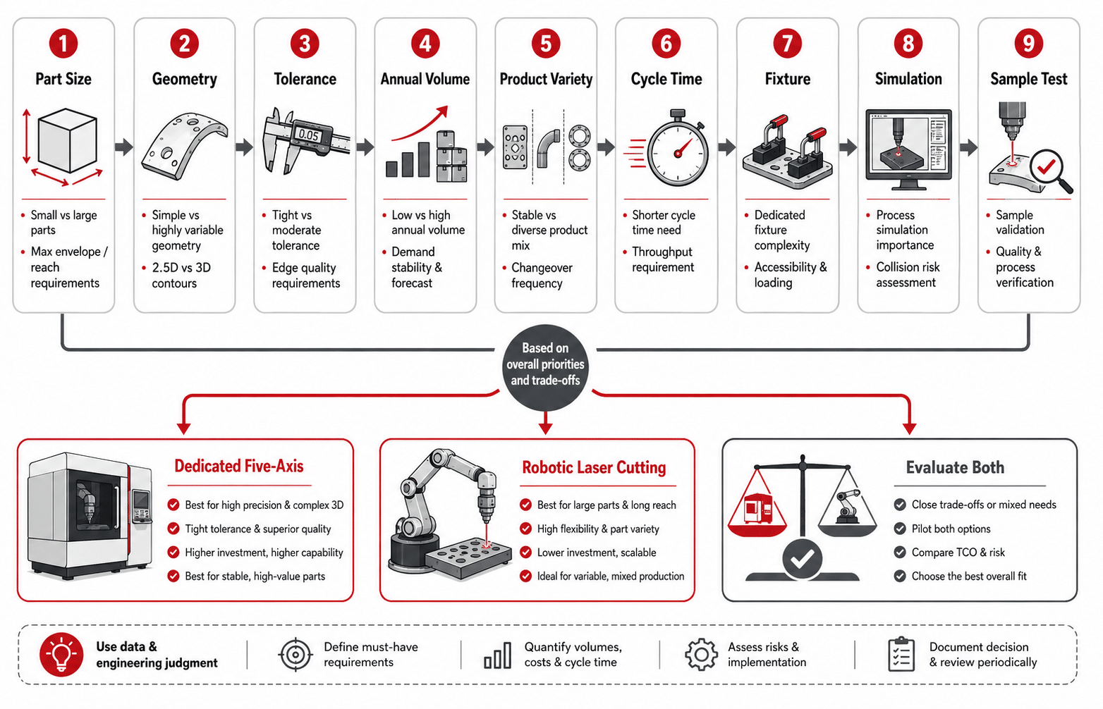
24. How to Choose Between the Two
Use the following process.
Step 1 — Provide the 3D Model
The supplier cannot reliably evaluate accessibility from overall dimensions alone.
Provide:
- STEP
- IGES
- Parasolid
- Other supported 3D CAD
Step 2 — Define the Material
Specify:
- Grade
- Thickness
- Coating
Step 3 — Identify All Cutting Features
Mark:
- Trim contours
- Holes
- Slots
- Bevels
- Recessed features
Step 4 — Define Tolerance
Identify critical dimensions separately from non-critical features.
Step 5 — Define Part Variation
Is the part:
- Stamped?
- Hot formed?
- Cast?
- Welded?
- Hydroformed?
Step 6 — Define Annual Volume
Include:
- Parts per year
- Parts per shift
- Number of shifts
- Product variants
Step 7 — Define Target Cycle Time
This influences whether a dedicated production platform is required.
Step 8 — Evaluate Accessibility
Simulate:
- Cutting head
- Fixture
- Machine
- Robot
- Part
Step 9 — Conduct Sample Cutting
Test actual representative parts.
Step 10 — Compare Complete Production Economics
Compare:
machine + fixture + automation + labor + maintenance + cycle time
25. What Should Be Tested During a Sample Evaluation?
Do not compare demonstration videos.
Use your actual part.
Evaluate Accessibility
Can the head reach:
- Every trim line?
- Deep features?
- Side-wall holes?
- Recessed contours?
Evaluate Accuracy
Measure:
- Hole location
- Trim position
- Overall geometry
- Feature-to-feature dimensions
Evaluate Edge Quality
Inspect:
- Dross
- Taper
- Incomplete cutting
- Oxidation
Evaluate Cycle Time
Record:
- Loading
- Clamping
- Cutting
- Repositioning
- Unloading
Evaluate Repeatability
Cut multiple components.
One good sample proves feasibility.
Repeated samples provide much more useful information about production stability.
26. Questions to Ask the Supplier
Before selecting a solution, ask:
- Can both architectures process our complete part?
- Which features are difficult to access?
- What working range is required?
- What robot reach would be required?
- Would an external axis be necessary?
- Which five-axis machine size would be required?
- What tolerance can be demonstrated on our part?
- What fixture is required?
- What is the expected complete cycle time?
- How is the machine calibrated?
- How is the robot calibrated?
- Is offline programming included?
- Is collision simulation included?
- Can part sensing be added?
- What automation can be integrated?
- What is the complete cell footprint?
- What maintenance is required?
- What spare parts should be stocked?
- Can repeated parts be tested?
- What is the estimated cost per finished part?
27. ZG Laser Five-Axis and Robotic Solutions
ZG Laser currently offers both dedicated five-axis and robotic 3D laser cutting solutions.
3D Five-Axis Platforms
The current five-axis portfolio includes several platforms for different production strategies:
- S-Auto Series — automotive hot-formed components and high-cycle production
- DF Series — general industrial 3D processing
- SF Series — prototypes and small-to-medium batches
- Compact Series — smaller layouts and flexible production
ZG Laser’s five-axis systems support trimming, hole cutting, bevel cutting and multi-angle processing of formed and irregular components.
Explore ZG Laser 3D Five-Axis Machines
ZG Laser also provides a robotic fiber-laser platform using an industrial articulated robot for flexible multi-angle processing of curved metal parts, tubes and automotive components.
Explore Robotic Laser Cutting Systems
Conclusion
Five-axis laser cutting and robotic laser cutting are not competing versions of exactly the same machine.
They are two different motion architectures for solving three-dimensional processing problems.
A dedicated five-axis machine is a strong option when production requires:
- Defined working envelope
- Repetitive 3D processing
- Dedicated fixtures
- Stable high-cycle production
- Automotive hot-forming applications
A robotic system deserves serious consideration when production requires:
- Large flexible reach
- Significant variation in part size
- Multiple workstations
- Flexible cell layouts
- Multi-purpose automation
Modern high-precision robots also mean that the old assumption that robots are automatically unsuitable for accurate 3D laser cutting is increasingly outdated. FANUC, for example, now offers robot platforms specifically engineered for high-precision 3D laser processing.
The correct decision should therefore be based on:
- Actual part geometry
- Required tolerance
- Working range
- Annual production volume
- Product variety
- Target cycle time
- Fixture requirements
- Complete cell cost
The best way to make the decision is to provide the supplier with your actual 3D model and evaluate both architectures before finalizing the equipment.
Not Sure Whether You Need a Five-Axis Machine or a Robot?
Send ZG Laser:
- Your 3D model
- Material and thickness
- Part dimensions
- Required trim paths
- Tolerance
- Annual volume
- Target cycle time
- Automation requirements
Our application team can evaluate cutting-head accessibility, working range, fixture requirements and production strategy before recommending a machine architecture.
Explore Robotic Laser Cutting Systems
Frequently Asked Questions
Is a five-axis laser cutting machine more accurate than a robot?
Not automatically. Dedicated machine tools and articulated robots use different motion structures, and accuracy depends on machine design, robot model, calibration, fixture and application. Modern high-precision robots are specifically available for 3D laser cutting applications.
What is the main advantage of a five-axis laser cutting machine?
A dedicated five-axis machine provides a controlled machine-tool platform for repeatable multi-angle processing of formed 3D parts. It is particularly established for automotive hot-formed component trimming.
What is the main advantage of robotic laser cutting?
Robotic systems provide flexible multi-axis reach and can be configured around different fixtures, positioners and large workpieces. KUKA specifically highlights flexibility as a key advantage of robotic cutting systems.
Can a robot cut automotive hot-formed parts?
Yes, when the robot, laser system, fixture and accuracy requirements are suitable. Robotic laser systems are used for complex 3D automotive-related cutting applications.
Which system is better for B-pillars?
Dedicated five-axis machines are a well-established solution for B-pillar trimming and other hot-formed automotive components.
Which is better for very large components?
Robotic systems often deserve stronger consideration where a large or flexible working envelope is needed, particularly when robots can be combined with external axes or positioners.
Do both systems require fixtures?
Yes. Accurate workholding remains important for both five-axis and robotic cutting because part location directly influences the finished cutting result.
Can five-axis laser cutting be used for small batches?
Yes. Compact and lower-investment 3D laser cells are available specifically for small-to-medium lot sizes, and ZG Laser’s current SF Series is also positioned around prototype and small-to-medium batch applications.
Is robotic laser cutting cheaper?
Not necessarily. The complete robot cell may require the robot, laser, cutting head, positioner, safety enclosure, software, integration and calibration. Compare complete production-cell investment and cost per finished part.
Should I test my actual part before selecting a system?
Yes. Actual sample testing is the best way to compare accessibility, cutting accuracy, cycle time, fixture design and repeated-part consistency.