A 3D five-axis laser cutting machine can look impressive in a brochure.
The specification may show:
- Large X/Y/Z travel
- High laser power
- Fast rotary axes
- Tight positioning accuracy
- Offline programming
- Automatic worktables
But none of these specifications alone proves that the machine can repeatedly process your actual part to the required quality and cycle time.
For complex applications such as:
- Hot-formed automotive components
- B-pillars
- Door rings
- Crossmembers
- Hydroformed tubes
- Curved sheet-metal components
- Aerospace parts
- Irregular 3D structures
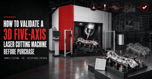
the most useful validation method is to move from specifications to an actual application test.
A structured validation project should answer several questions:
- Can the cutting head reach every required feature?
- Can the fixture locate the part consistently?
- Can the laser process produce the required edge and hole quality?
- Can critical dimensions meet the drawing requirement?
- Can the result be repeated across multiple parts?
- Can the complete production cycle meet the required output?
- Does the delivered machine match the configuration used during validation?
ZG Laser’s current five-axis project-evaluation process already recommends drawing review, process and fixture evaluation, machine configuration review and sample testing for critical projects.
The next step is to make that validation process measurable.
The key principle is:
One successful sample proves feasibility. Repeated samples begin to demonstrate repeatability. Production capability requires a separately defined validation plan.
1. Why Sample Testing Matters Before Buying a Five-Axis Machine
A conventional sheet-metal cutting project can often be evaluated using well-established material and thickness data.
Three-dimensional cutting has more variables.
The result depends on:
- Part geometry
- Cutting-head orientation
- Machine travel
- Rotary-axis motion
- Fixture
- Workpiece variation
- TCP calibration
- Offline program
- Collision clearance
- Laser parameters
- Measurement method
A machine may have sufficient nominal travel but fail to reach one recessed hole.
It may cut a perfect contour on a rigid demonstration sample but struggle with a variable hot-formed production part.
It may produce acceptable dimensions while loaded in the fixture but fail after unclamping because the component relaxes.
This is why the actual application should be tested before a critical purchase is approved.
How to choose a 3D five-axis laser cutting machine
2. Sample Testing, FAT and SAT Are Different
These three stages should not be mixed together.
Sample Testing
Usually occurs during application evaluation.
Its main purpose is to determine:
Can the proposed process manufacture the part?
It may happen before the final order.
FAT — Factory Acceptance Test
FAT takes place at the supplier’s factory before shipment.
Its purpose is to verify that the ordered equipment and agreed application requirements have been met before the machine leaves the supplier.
SAT — Site Acceptance Test
SAT takes place after installation at the customer’s factory.
Its purpose is to verify that:
- Installation
- Utilities
- Calibration
- Safety
- Production conditions
are correct at the final site.
Quick Comparison
| Stage | Main Question |
|---|---|
| Sample Test | Can the proposed process make the part? |
| Repeated Sample Test | Can the process produce similar results repeatedly? |
| FAT | Does the completed machine meet the agreed pre-shipment requirements? |
| SAT | Does the installed machine operate correctly at the customer’s factory? |
The exact scope should always be defined in the purchase agreement.
There is no single universal FAT checklist that applies to every custom five-axis laser project.
3. What Should the Customer Provide Before Sample Testing?
The quality of the test depends heavily on the information supplied.
At minimum, provide:
Engineering Data
- 3D CAD model
- 2D drawing
- Drawing revision
- Part number
- Material grade
- Material thickness
- Coating, if applicable
Cutting Requirements
- Final trim lines
- Holes
- Slots
- Bevels
- Critical dimensions
- Edge-quality requirements
Production Requirements
- Annual volume
- Parts per shift
- Number of shifts
- Target cycle time
- Expected product variants
- Manual or automated loading
Quality Requirements
- Tolerances
- Inspection datums
- Inspection method
- Required reports
Physical Parts
For formed components, actual production samples are extremely valuable.
The nominal CAD model cannot fully show:
- Springback
- Surface variation
- Flange variation
- Weld distortion
- Real loading behavior
ZG Laser’s current project-evaluation page similarly asks buyers to provide drawings, material, thickness, maximum size, required accuracy and production capacity before a configuration is recommended.
4. Use the Correct Drawing Revision
Before cutting anything, confirm:
Part CAD Revision = 2D Drawing Revision = Test Requirement
This sounds basic, but revision errors can invalidate an entire test.
A useful project record might contain:
Customer: ABC Automotive
Part Number: BP-RH-02
3D CAD Revision: F
2D Drawing Revision: F
Fixture Revision: B
NC Program Revision: P04
Test Date: 2026-xx-xx
If the drawing changes during the project, the old result should not automatically be treated as validation of the new revision.
5. Test a Representative Production Part
Do not validate a machine using only a simple supplier demonstration sample.
A generic demo may prove that:
- The laser works
- The axes move
- The machine can perform 3D cutting
It does not prove that the machine can process your specific component.
A representative validation part should contain the important production challenges.
These may include:
- Long trim contours
- Small holes
- Recessed holes
- Angled surfaces
- Tight tolerance features
- Difficult fixture clearance
- Multiple cutting-head orientations
For hot-formed automotive projects, use production-representative formed components whenever possible.
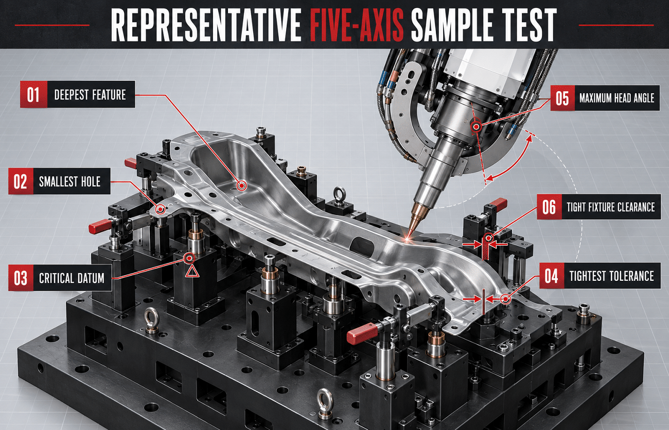
6. Test the Most Difficult Feature, Not the Easiest
Imagine a component contains:
- 20 simple holes
- 3 external trim contours
- 1 deeply recessed side-wall hole
The recessed hole should be one of the primary validation targets.
Similarly, identify:
- Smallest hole
- Tightest positional tolerance
- Maximum required head angle
- Deepest recess
- Longest cutting path
- Narrowest clamp clearance
- Most difficult trim transition
A machine that performs 95% of the geometry but cannot process one functionally critical feature is not a successful solution.
This principle is already included in ZG Laser’s current five-axis buyer guide: difficult access areas should drive feasibility testing rather than only easy external contours.
7. Define Acceptance Criteria Before Cutting
Do not perform the test first and decide afterward what counts as acceptable.
Before sample cutting, both sides should agree on measurable criteria.
Examples include:
Geometry
- Hole position
- Hole diameter
- Slot size
- Trim-line position
- Feature-to-feature distance
Cutting Quality
- Complete cut
- Dross
- Edge appearance
- Taper
- Oxidation
- Local heat damage
Production
- Complete cycle time
- Loading method
- Operator intervention
- Alarm frequency during test
Repeatability
- Number of repeated parts
- Features to be measured
- Acceptable part-to-part variation
The important principle is:
Acceptance criteria should be agreed before the results are known.
This protects both buyer and supplier.
8. Separate Critical Features From General Features
Not every dimension needs the same acceptance priority.
Identify:
Critical-to-Function Features
Examples:
- Assembly locating holes
- Mounting holes
- Weld interfaces
- Datum-related trims
General Features
Examples:
- Clearance openings
- Non-functional trim edges
- Scrap contours
This helps prevent a test from focusing heavily on an easy cosmetic edge while ignoring a critical hole position.
A useful FAT drawing can visually mark critical features.
9. Agree on the Measurement Datum
A dimension has meaning only relative to its defined datum system.
Before testing, agree on:
- Primary datum
- Secondary datum
- Tertiary datum
- Measurement coordinate system
The manufacturing fixture and inspection process do not necessarily need to be identical, but their datum relationship must be clearly understood.
Renishaw’s process-setting guidance similarly emphasizes establishing the relationship between machine, part and coordinate system through datum features before production begins.
10. Define Free-State vs Constrained Measurement
This is particularly important for formed sheet-metal parts.
A component may be measured:
- Freely supported
- On a checking fixture
- On the laser cutting fixture
- Under defined clamping conditions
The result can differ.
Example
A thin formed panel may meet dimensional requirements while constrained by the cutting fixture but move slightly after unclamping.
This does not automatically indicate a machine problem.
The drawing and customer quality standard should define the required inspection state.
Do not wait until FAT to discover that:
Supplier measured on fixture
while:
Customer expected free-state measurement.
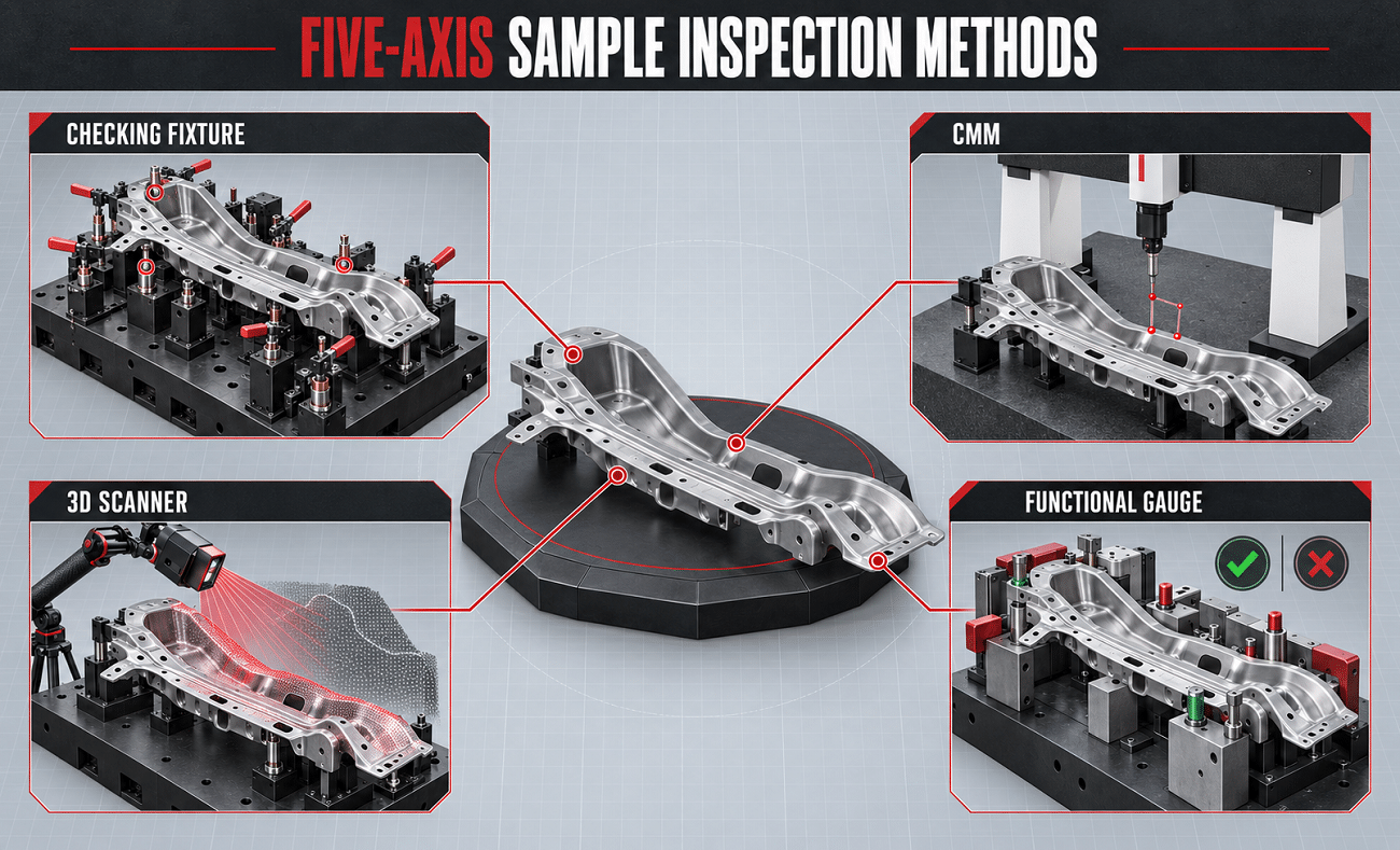
11. Agree on the Inspection Equipment
Possible measurement methods include:
- Calipers
- Height gauges
- Go/no-go gauges
- Functional gauges
- Checking fixtures
- CMM
- 3D scanning
- Vision systems
Choose the method according to:
- Tolerance
- Geometry
- Feature accessibility
- Customer quality procedure
For tight dimensional criteria, the measuring method itself must be sufficiently capable and properly calibrated.
Do not claim machine failure from measurement data whose uncertainty is too large for the tolerance being evaluated.
12. Validate the Fixture Before Judging the Machine
A poor fixture can make a good machine appear inaccurate.
Before evaluating cut dimensions, verify:
- Correct datum strategy
- Locator condition
- Fixture installation
- Clamp sequence
- Clamp force
- Part seating
- Fixture repeatability
The fixture should locate the component consistently without forcing it into an artificial geometry.
13. Perform a Repeat-Loading Test
Before cutting several production samples, it can be useful to test the fixture itself.
A simple method is:
- Load the same component.
- Clamp it.
- Measure selected reference positions.
- Unload it.
- Reload the same component.
- Repeat.
This helps separate:
Fixture loading variation
from:
Part-to-part incoming variation.
If the same component does not return to the same position consistently, cutting more samples will not solve the underlying fixture problem.
14. Verify Cutting-Head Accessibility
The sample test should confirm that the complete laser head can reach every feature.
Check:
- Nozzle clearance
- Head-body clearance
- Clamp clearance
- Rotary-axis range
- Lead-in motion
- Lead-out motion
- Rapid repositioning
- Deep feature access
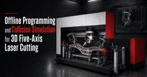
A successful offline simulation is very valuable, but the real fixture and machine should still be verified before full-speed production.
Offline programming and collision simulation
15. Record the Exact Machine Configuration Used for Testing
This is essential.
The validation record should identify:
- Machine model
- Machine serial number, if available
- Laser source
- Laser power
- Cutting head
- CNC/control
- Worktable configuration
- Software
- Fixture
- Assist-gas system
Why?
Imagine a sample is tested successfully using:
6000W + production rotary table + one head configuration
but the commercial quotation later specifies:
3000W + different table + different cutting head
The original result should not automatically be considered proof of the quoted configuration.
A sample test validates a specific process configuration.
16. Record Process Parameters
Important parameters can include:
- Laser power
- Cutting speed
- Focus
- Assist gas
- Gas pressure
- Nozzle
- Stand-off distance
- Piercing parameters
- Cutting direction
- Head orientation
This creates a process record.
Without these details, a successful sample may be difficult to reproduce later during FAT or SAT.
17. Record the Fixture Revision
Fixtures often change during development.
For example:
Rev A
→ clamp interferes with cutting head.
Rev B
→ clamp moved.
Rev C
→ new support added to improve repeatability.
The test report should therefore identify the fixture revision used.
Otherwise, a later FAT may unknowingly use a modified fixture and be compared with results produced under different conditions.
18. Record the NC Program Revision
The same principle applies to programming.
A production record should contain:
- Part revision
- Fixture revision
- NC program revision
- Parameter revision
This is particularly important after:
- Collision-clearance modifications
- Cycle-time optimization
- Kerf compensation changes
- Coordinate corrections
A useful production rule is:
Approved part + approved fixture + approved program + approved parameters = validated process configuration.
19. Measure Complete Cycle Time
Do not validate productivity using laser-on time alone.
Record:
Total Cycle Time = Loading + Positioning + Clamping + Table Movement + Piercing + Cutting + Repositioning + Unclamping + Unloading
For rotary-table production, also determine whether loading can occur in parallel with cutting.
Separate the Major Time Components
For example:
| Stage | Time |
|---|---|
| Loading | — |
| Clamping | — |
| Table indexing | — |
| Cutting | — |
| Unclamping | — |
| Unloading | — |
| Total cycle | — |
Do not enter hypothetical values in the published article; use the real project data during validation.
20. Record Operator Intervention
A sample may look successful while requiring constant manual assistance.
Record whether the operator needed to:
- Reposition the part
- Clear scrap
- Reset alarms
- Modify the program
- Manually adjust the fixture
- Clean the nozzle
- Stop the machine
A production process requiring repeated intervention may not achieve the same throughput as an ideal demonstration cycle.
21. One Successful Sample Proves Feasibility
A single successful sample answers an important question:
Can this machine and process manufacture the part under these conditions?
That is valuable.
But it does not prove:
- Long-term repeatability
- Process capability
- Shift-to-shift stability
- Fixture durability
Therefore, describe one part correctly:
Feasibility sample
rather than:
Mass-production capability proof.
22. Repeated Parts Begin to Evaluate Repeatability
The next step is to process multiple components using the same approved conditions.
Measure the same critical features on each part.
Record:
- Hole position
- Trim position
- Key dimensions
- Edge condition
- Cycle time
This allows you to see whether results are:
- Stable
- Drifting
- Randomly varying
Important
A small group of consecutive samples can provide useful repeatability evidence.
It should not automatically be presented as a formal statistical process-capability study.
If Cp, Cpk, Pp, Ppk or another capability metric is contractually required, define:
- Sample quantity
- Sampling period
- Measurement method
- Production conditions
- Calculation method
- Acceptance value
before the study begins.
23. Distinguish Machine Repeatability From Production Repeatability
Part-to-part variation can come from several sources.
Conceptually:
Production Variation = Machine + Calibration + Fixture + Incoming Part + Laser Process + Measurement
For example, if hole position varies between samples, possible causes include:
- Fixture loading
- Formed-part variation
- TCP calibration
- Coordinate system
- Measurement variation
Do not immediately conclude that every variation is machine-axis error.
What determines 3D five-axis laser cutting accuracy
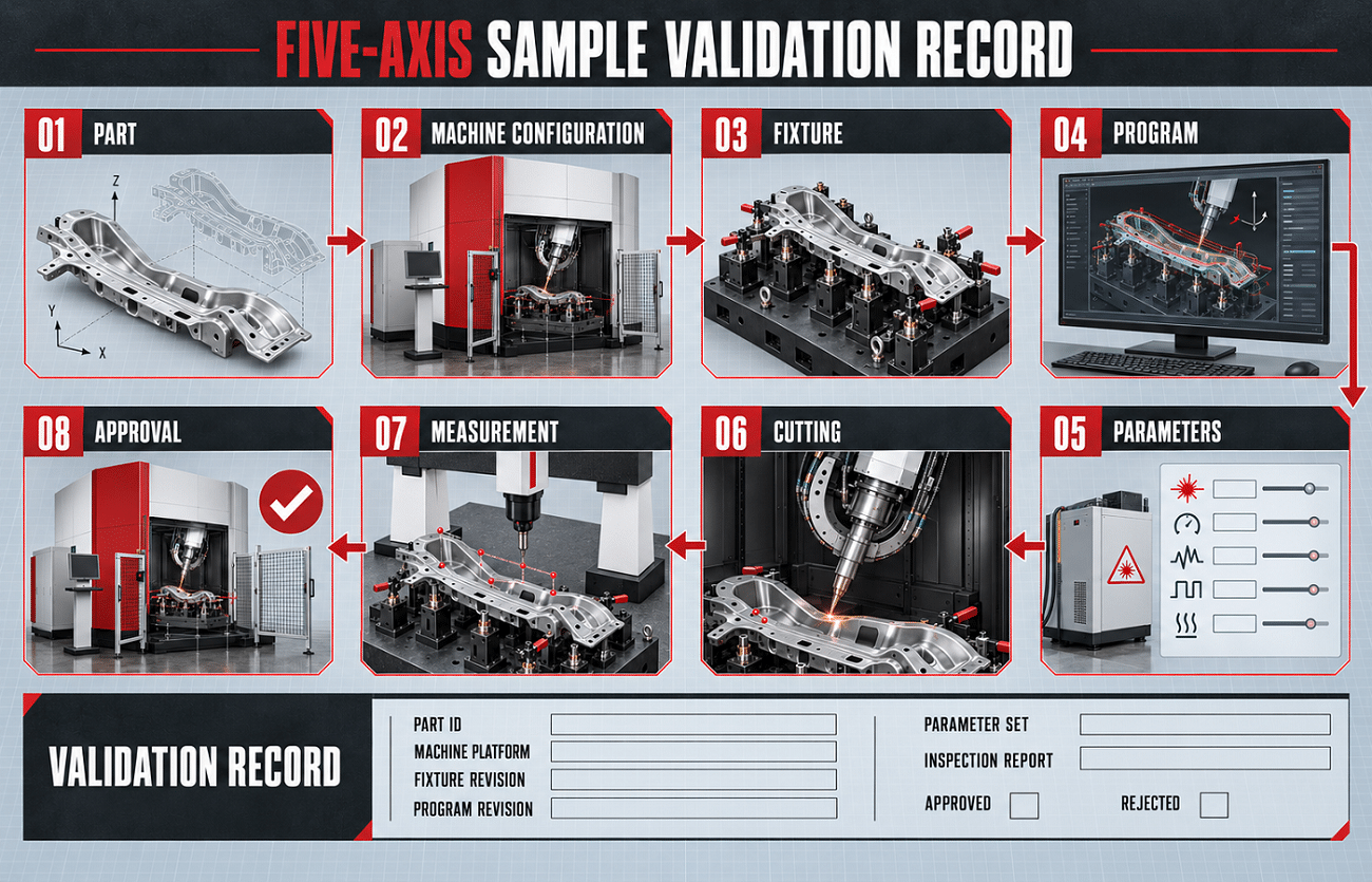
24. Create a Sample Validation Record
A structured report may include:
| Item | Record |
|---|---|
| Customer | Project name |
| Part | Part number |
| Drawing | Revision |
| CAD | Revision |
| Material | Grade |
| Thickness | Actual |
| Machine | Model |
| Laser | Source / power |
| Cutting head | Model/configuration |
| Fixture | Revision |
| NC program | Revision |
| Assist gas | Type |
| Test part | Sample ID |
| Cycle time | Complete cycle |
| Inspection method | CMM / gauge / etc. |
| Measurement result | Recorded values |
| Edge quality | Result |
| Operator intervention | Record |
| Deviations | Record |
This report becomes useful later during FAT.
25. What Is a Factory Acceptance Test?
A Factory Acceptance Test, or FAT, is performed at the supplier’s facility before shipment.
For a custom five-axis laser project, FAT should normally verify two levels.
Level 1 — Machine-Level Acceptance
Does the delivered machine match the ordered configuration and operate correctly?
Level 2 — Application-Level Acceptance
Can the completed system execute the agreed customer process?
This distinction matters.
A machine can pass a mechanical FAT while still failing the customer’s application requirement.
For application-specific equipment, both levels should be considered in the acceptance agreement.
26. Machine-Level FAT
Typical machine-level FAT items may include:
Configuration
- Correct machine model
- Correct axis travel
- Correct laser source
- Correct laser power
- Correct cutting head
- Correct worktable
Machine Function
- Axis operation
- Rotary-axis operation
- Worktable operation
- Laser operation
- CNC/control
Safety
- Door interlocks
- Emergency stops
- Enclosure
- Safety functions
Supporting Systems
- Dust extraction interface
- Gas system
- Cooling
- Pneumatics
- Electrical cabinet
Software
- Offline programming package
- Postprocessor
- Machine configuration
- Licenses
The exact list should match the signed technical agreement.
27. Application-Level FAT
For a customized 3D cutting project, this is often the more valuable section.
Possible acceptance items include:
- Correct customer part
- Correct fixture revision
- Approved NC program
- Approved process parameters
- Head accessibility
- Cutting quality
- Critical dimensions
- Repeated sample results
- Complete cycle time
- Loading/unloading method
The customer and supplier should agree which items are binding acceptance criteria and which are engineering observations.
28. Suggested Five-Axis FAT Checklist
Machine Configuration
☐ Machine model confirmed
☐ Laser power confirmed
☐ Cutting head confirmed
☐ Axis travel confirmed
☐ Rotary axes confirmed
☐ Worktable confirmed
Safety & Utilities
☐ Safety doors/interlocks tested
☐ Emergency stop tested
☐ Cooling system checked
☐ Gas system checked
☐ Extraction interface checked
Software
☐ Offline software confirmed
☐ Machine model confirmed
☐ Postprocessor confirmed
☐ NC program transfer tested
☐ Collision simulation workflow verified
Fixture
☐ Correct fixture revision
☐ Fixture installation verified
☐ Datums checked
☐ Clamp operation tested
☐ Part loading tested
Application
☐ Correct drawing revision
☐ Correct material
☐ Critical features processed
☐ Cutting quality inspected
☐ Dimensions measured
Production
☐ Complete cycle measured
☐ Repeated samples performed as agreed
☐ Operator intervention recorded
☐ Scrap handling reviewed
Documentation
☐ Test report
☐ Measurement report
☐ Machine configuration list
☐ Software information
☐ Training documentation
☐ Maintenance documentation
29. The FAT Checklist Should Be Project-Specific
Do not copy an online FAT template and assume it is sufficient.
A B-pillar production line and a prototype aerospace cell may require very different acceptance tests.
The checklist should reflect:
- Contract
- Part
- Production volume
- Automation
- Quality requirement
- Destination
If the project does not require a particular test, do not create unnecessary acceptance risk.
If a requirement is critical, make sure it is written into the agreement before machine completion.
30. What Should Be in the FAT Report?
A professional FAT record can contain:
Machine Identification
- Manufacturer
- Model
- Serial number
- Laser source
- Power
Project Identification
- Customer
- Part number
- Drawing revision
Production Configuration
- Fixture revision
- NC revision
- Parameter revision
Test Conditions
- Material
- Thickness
- Gas
- Inspection method
Results
- Critical dimensions
- Cutting-quality observations
- Cycle time
- Repeated-part results
Deviations
- Open items
- Corrective actions
- Re-test requirement
Sign-Off
- Supplier
- Customer or authorized representative
- Date
Photographs or video may also be included where appropriate.
31. FAT Should Verify the Configuration That Will Be Shipped
This is critical.
The system tested during FAT should correspond to the system being delivered.
If a temporary component is used during testing, document it.
Examples:
- Different laser source
- Temporary fixture
- Prototype cutting head
- Alternative software license
The buyer should know whether the FAT result represents:
final delivery configuration
or:
temporary engineering configuration.
32. What Happens If the Sample Fails?
A failed test does not automatically mean the entire machine concept is wrong.
Classify the problem first.
Geometry Failure
Examples:
- Hole offset
- Trim shift
Check:
- Datum
- Fixture
- Coordinate system
- TCP
- Calibration
- NC program
Edge-Quality Failure
Examples:
- Dross
- Rough edge
- Incomplete cut
Check:
- Laser power
- Focus
- Speed
- Assist gas
- Nozzle
Collision or Accessibility Failure
Check:
- Head orientation
- Fixture
- Clamp
- Machine envelope
- Offline program
Cycle-Time Failure
Check:
- Cutting sequence
- Laser power
- Rotary movement
- Table architecture
- Loading process
Repeatability Failure
Check:
- Fixture loading
- Incoming-part variation
- Machine condition
- Measurement system
A structured root-cause investigation is more useful than random parameter adjustment.
33. Do Not Hide a Failure by Changing the Acceptance Criterion
Suppose the agreed hole-position requirement is X.
After testing, the result does not meet X.
The wrong response is:
“Maybe X was too strict; let’s call this acceptable.”
unless the customer engineering team formally changes the requirement.
Likewise, the buyer should not introduce a previously undisclosed tighter requirement only after seeing successful results.
The fair principle is:
Agree first. Test second. Judge against the agreed criteria.
34. Supplier Demo Sample vs Customer Production Sample
These two samples serve different purposes.
Supplier Demo Sample
Useful for showing:
- Machine movement
- General cutting ability
- Surface quality
- Complex geometry
It is primarily a capability demonstration.
Customer Production Sample
Useful for evaluating:
- Actual geometry
- Actual tolerances
- Fixture
- Cycle time
- Production feasibility
For equipment purchasing, the second is much more valuable.
35. What About Remote FAT?
Remote FAT can be practical when:
- Travel is difficult
- The project is relatively standardized
- Acceptance items can be documented clearly
A remote FAT package may include:
- Live video
- Recorded cycle
- Machine configuration photographs
- Measurement report
- Sample photographs
- Test files
- Finished samples shipped to the customer
Improve Remote FAT Credibility
Show:
- Part identification
- Drawing revision
- Machine identification
- Continuous cycle where relevant
- Measuring equipment
- Actual measurement values
Avoid relying only on edited promotional video.
36. When Is On-Site FAT at the Supplier More Valuable?
Customer attendance at the supplier’s factory deserves consideration for:
- High-value equipment
- Custom fixtures
- Automotive production cells
- Strict cycle-time requirements
- Critical dimensional projects
- New process development
Being physically present can make it easier to review:
- Machine configuration
- Loading
- Cutting
- Measurement
- Software
- Training
But attendance should be decided according to project risk rather than treated as mandatory for every machine.
37. FAT Is Not the End: The Machine Still Needs SAT
After FAT approval, the machine is:
- Disassembled where necessary
- Packed
- Transported
- Installed again
The final factory introduces different:
- Foundation
- Temperature
- Electricity
- Gas supply
- Compressed air
- Extraction
- Network
- Operator environment
Therefore, final site verification is still important.
38. What Is a Site Acceptance Test?
SAT verifies the installed system at the customer’s factory.
Typical SAT areas include:
Installation
- Machine location
- Leveling
- Mechanical installation
- Electrical installation
Utilities
- Electrical supply
- Assist gas
- Compressed air
- Cooling
- Extraction
Machine Condition
- Calibration
- Axis operation
- Safety
Application
- Fixture installation
- NC program
- Part cutting
- Dimensional verification
Training
- Operator
- Programmer
- Maintenance personnel
39. FAT vs SAT
| FAT | SAT |
|---|---|
| Supplier factory | Customer factory |
| Before shipment | After installation |
| Supplier utilities | Customer utilities |
| Confirms ordered machine | Confirms installed machine |
| Application test under supplier conditions | Application test under real site conditions |
| Pre-shipment acceptance | Final site acceptance |
The exact commercial meaning of FAT and SAT should be defined in the contract.
Do not assume that the terminology automatically creates the same obligations in every purchase agreement.
40. Why Calibration Should Be Checked After Installation
The relationship between:
- Linear axes
- Rotary axes
- Cutting head
- Fixture
- Coordinate system
must remain correct.
Transport and installation are therefore followed by machine setup and verification.
Renishaw’s process-control guidance emphasizes establishing machine, fixture, rotary-axis and workpiece relationships before machining, while its broader process-control framework separates process setting from post-process inspection.
For a five-axis laser system, follow the machine manufacturer’s installation and calibration procedure rather than simply copying the supplier-factory offsets.
41. Verify the Customer’s Utilities During SAT
A process validated during FAT can behave differently if the customer’s utilities are insufficient.
Check:
Assist Gas
- Type
- Pressure
- Flow
- Purity where specified
Compressed Air
- Pressure
- Flow
- Dryness
- Filtration
Electricity
- Voltage
- Capacity
- Stability
Extraction
- Airflow
- Ducting
- Filter installation
Environmental Conditions
Where relevant:
- Temperature
- Humidity
- Dust
These factors belong to the complete production system.
42. Compare FAT and SAT Results
For the agreed validation part, compare:
- Critical dimensions
- Cutting quality
- Complete cycle time
- Machine behavior
The goal is not necessarily to reproduce every microscopic measurement identically.
The goal is to confirm that the installed process meets the agreed acceptance requirement.
If results differ materially, investigate:
- Calibration
- Fixture installation
- Utilities
- Parameters
- Material batch
- Measurement method
before changing the acceptance criteria.
43. Digital Simulation Supports Validation—but Does Not Replace It
Offline simulation can significantly reduce machine-side prove-out.
Modern CNC digital-twin systems can model:
- Machine kinematics
- Workpiece
- Fixture
- Tooling
- NC execution
and detect potential collisions before production. Siemens’ current Run MyVirtual Machine and NX machine-simulation solutions specifically support complete machine models, NC validation, collision detection and realistic cycle-time calculation.
This is extremely valuable.
But simulation cannot fully reproduce every physical condition, including:
- Incoming-part variation
- Fixture contamination
- Flexible scrap
- Clamping deformation
- Gas behavior
Therefore:
Virtual validation reduces physical risk; physical validation confirms the real process.
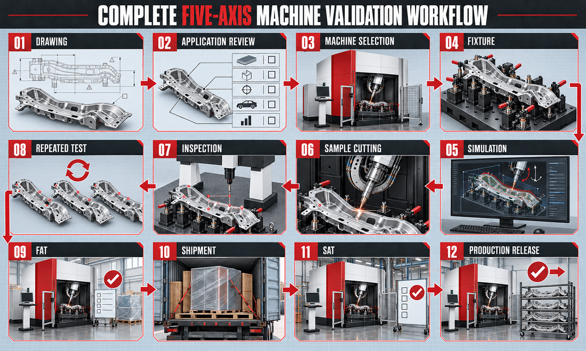
44. A Complete Validation Workflow
A strong project can follow this sequence:
Customer Drawing
↓
Application Review
↓
Machine Configuration
↓
Fixture Concept
↓
Offline Programming
↓
Collision Simulation
↓
Sample Cutting
↓
Dimensional Inspection
↓
Repeated Samples
↓
Configuration Approval
↓
Machine Manufacturing
↓
FAT
↓
Shipment
↓
Installation & Calibration
↓
SAT
↓
Production Training
↓
Production Release
This is much more reliable than:
Buy machine → ship machine → see whether the part works.
45. Recommended Acceptance Criteria Categories
A practical technical agreement can organize acceptance into six areas.
1. Machine
- Configuration
- Working range
- Functions
2. Safety
- Interlocks
- Emergency functions
- Enclosure
3. Software
- Programming
- Postprocessor
- Simulation
4. Application
- Part
- Fixture
- Cutting geometry
5. Quality
- Critical dimensions
- Edge requirements
- Repeatability
6. Productivity
- Complete cycle time
- Loading strategy
- Operator intervention
This structure helps prevent important requirements from being buried inside a long machine specification sheet.
46. Do Not Use Vague Acceptance Language
Avoid contractual statements such as:
“Good cutting quality.”
“High accuracy.”
“Fast production.”
These are difficult to verify.
Where commercially necessary, replace them with agreed measurable criteria such as:
- Drawing-defined dimensional tolerance
- Agreed inspection method
- Agreed complete cycle-time method
- Agreed acceptable edge condition
Use photographs or approved reference samples if visual criteria are difficult to describe numerically.
47. Cycle-Time Acceptance Must Define the Starting and Ending Point
A claimed 90-second cycle can mean very different things.
Does the clock start when:
- The operator touches the part?
- Clamping finishes?
- Laser turns on?
Does it stop when:
- Laser turns off?
- Table returns?
- Finished part is removed?
For meaningful comparison, define:
Cycle Start
and:
Cycle End
before FAT.
For example:
From start of loading of one production part to the point at which the machine is ready to begin the next equivalent cycle.
The exact definition should reflect the customer’s production system.
48. Define Whether Manual Actions Are Included
If cycle acceptance is important, document:
- Number of operators
- Manual loading
- Manual scrap removal
- Manual inspection
- Manual nozzle cleaning
Otherwise, two tests can claim the same machine cycle while using very different labor.
49. What Information Should the Buyer Receive After Validation?
For an application-specific project, useful handover information may include:
- Approved machine configuration
- Approved fixture revision
- Approved NC program
- Approved parameter set
- FAT report
- Measurement report
- Training documents
- Maintenance guidance
- Software/license information
- Backup files
Not every project requires every document, but the scope should be agreed before shipment.
50. Final Pre-Purchase Validation Checklist
Before approving a critical five-axis project, confirm:
Part
- Correct CAD revision
- Correct drawing revision
- Actual material tested
- Representative sample used
- Difficult features included
Acceptance
- Critical dimensions agreed
- Datum system agreed
- Measurement state agreed
- Inspection equipment agreed
- Cutting-quality criteria agreed
- Cycle-time definition agreed
Fixture
- Fixture concept verified
- Repeat-loading checked
- Clamp deformation reviewed
- Cutting-head clearance verified
Machine
- Exact test configuration recorded
- Laser power recorded
- Cutting head recorded
- Worktable recorded
Programming
- NC revision recorded
- Fixture revision recorded
- Collision simulation completed
- Process parameters recorded
Validation
- Feasibility sample completed
- Repeated samples completed if required
- Results documented
- Deviations closed or accepted
FAT
- Machine FAT scope agreed
- Application FAT scope agreed
- Documentation scope agreed
- Witness method agreed
SAT
- Installation scope agreed
- Utility requirements confirmed
- Calibration procedure defined
- Site test criteria defined
Conclusion
A five-axis laser cutting machine should not be validated by a brochure specification or one attractive demonstration video.
The strongest purchasing decision is based on a structured sequence of:
representative sample testing → dimensional inspection → repeated verification → FAT → SAT
Each stage answers a different question.
A single sample answers:
Can the process make the part?
Repeated parts begin to answer:
Can the process produce similar results consistently?
FAT answers:
Does the completed machine match the agreed pre-shipment machine and application requirements?
SAT answers:
Does the installed system perform correctly under the customer’s real factory conditions?
The most important rule is to define acceptance criteria before the test begins.
That includes:
- Drawing revision
- Critical dimensions
- Datums
- Measurement method
- Fixture
- Machine configuration
- Cycle-time method
- Number of validation parts
A successful five-axis purchase is therefore not only about selecting the right machine.
It is about creating an agreed and traceable path from:
customer drawing
to:
validated production process.
Validate Your 3D Part Before Ordering a Five-Axis Machine
Send ZG Laser:
- Your 3D CAD model
- 2D drawing
- Actual formed sample
- Material and thickness
- Critical dimensions
- Required tolerances
- Annual production volume
- Target cycle time
Our application team can evaluate:
- Cutting-head accessibility
- Machine configuration
- Fixture requirements
- Offline programming
- Sample-testing strategy
- Inspection requirements
before the final machine configuration is approved.
Frequently Asked Questions
Should I request sample cutting before buying a five-axis laser machine?
For critical or custom 3D applications, sample testing is strongly recommended because it can verify cutting-head accessibility, fixture strategy, dimensional results, edge quality and production feasibility on the actual part.
Is one successful sample enough to approve a machine?
It can demonstrate feasibility, but it does not by itself prove repeated production stability. Repeated parts should be evaluated when repeatability is important.
How many samples should be tested?
There is no universal number for every project. The quantity should be defined according to production risk, tolerance, volume and the purpose of the test. A formal process-capability study requires a separately defined statistical plan.
What should be measured during a five-axis sample test?
Typical items include critical hole positions, hole sizes, trim-line locations, slots, edge condition and complete cycle time. The exact criteria should come from the customer’s drawing and production requirements.
What is FAT for a laser cutting machine?
FAT means Factory Acceptance Test. It is normally performed at the supplier’s factory before shipment to verify the agreed machine configuration, operation and, where specified, the customer’s application requirements.
Is FAT the same as sample testing?
No. Sample testing often occurs during process and equipment evaluation. FAT normally verifies the completed ordered machine before shipment.
What is SAT?
SAT means Site Acceptance Test. It is performed after installation at the customer’s factory to verify machine installation, utilities, calibration and agreed production requirements under real site conditions.
Should FAT include actual customer parts?
For an application-specific five-axis project, including the agreed customer part can make FAT much more meaningful because machine operation alone does not prove the production application.
Should cycle time be part of FAT?
If cycle time is an important purchasing requirement, it should be explicitly defined in the technical agreement, including what actions are included in the measured cycle.
Why must the measurement datum be agreed before testing?
Because the reported feature position depends on its datum system. Different inspection references can produce different interpretations of the same component.
Can a part pass while clamped but fail after it is removed?
Yes. Flexible or formed components may change shape after unclamping. The required inspection state should therefore be defined before acceptance testing.
Does offline collision simulation eliminate the need for a physical first test?
No. Digital simulation can substantially reduce collision and programming risk, but physical validation is still needed to account for real fixtures, incoming-part variation, process behavior and other physical conditions.
What if the FAT sample fails?
First identify whether the problem relates to geometry, fixture, calibration, cutting parameters, collision/accessibility, cycle time or incoming-part variation. Correct the root cause and repeat the agreed test where necessary.
Should the machine tested during FAT be the exact machine shipped?
The FAT should clearly identify the machine and configuration being accepted. Any temporary or substitute component used during testing should be documented.
What should be included in the final FAT report?
Depending on the project, it can include machine identification, customer part revision, fixture revision, NC program revision, test conditions, measurement results, cycle time, deviations, corrective actions and sign-off.