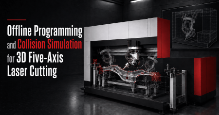
Programming a conventional flat-sheet laser cutter is relatively straightforward.
The workpiece is flat.
The cutting head normally remains perpendicular to the sheet.
And most cutting paths exist in a two-dimensional X-Y plane.
A 3D five-axis laser cutting machine creates a very different programming problem.
The cutting head may need to:
- Move in X, Y and Z simultaneously
- Rotate through two additional axes
- Follow a curved surface
- Approach holes from different directions
- Trim deep flanges
- Avoid clamps and locating pins
- Transition between steep surface angles
- Maintain suitable nozzle-to-part distance
- Stay within rotary-axis travel limits
At the same time, the programmer must consider:
- The real workpiece
- The fixture
- The cutting head
- The machine structure
- Worktable
- Safety enclosure
- Cutting sequence
- Laser parameters
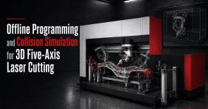
This is why offline programming and collision simulation are so important in 3D laser cutting.
TRUMPF’s current TruTops Cell software is designed specifically for offline 3D laser processing. It supports CAD import, fixture programming, NC generation, path optimization and collision checking before the program reaches the machine.
The objective is not simply to create a cutting path.
It is to create a program that is:
geometrically correct + physically reachable + collision-free + process-capable + efficient to execute.
1. What Is Offline Programming?
Offline programming means creating and validating the laser processing program on a separate computer rather than developing the entire program directly at the machine.
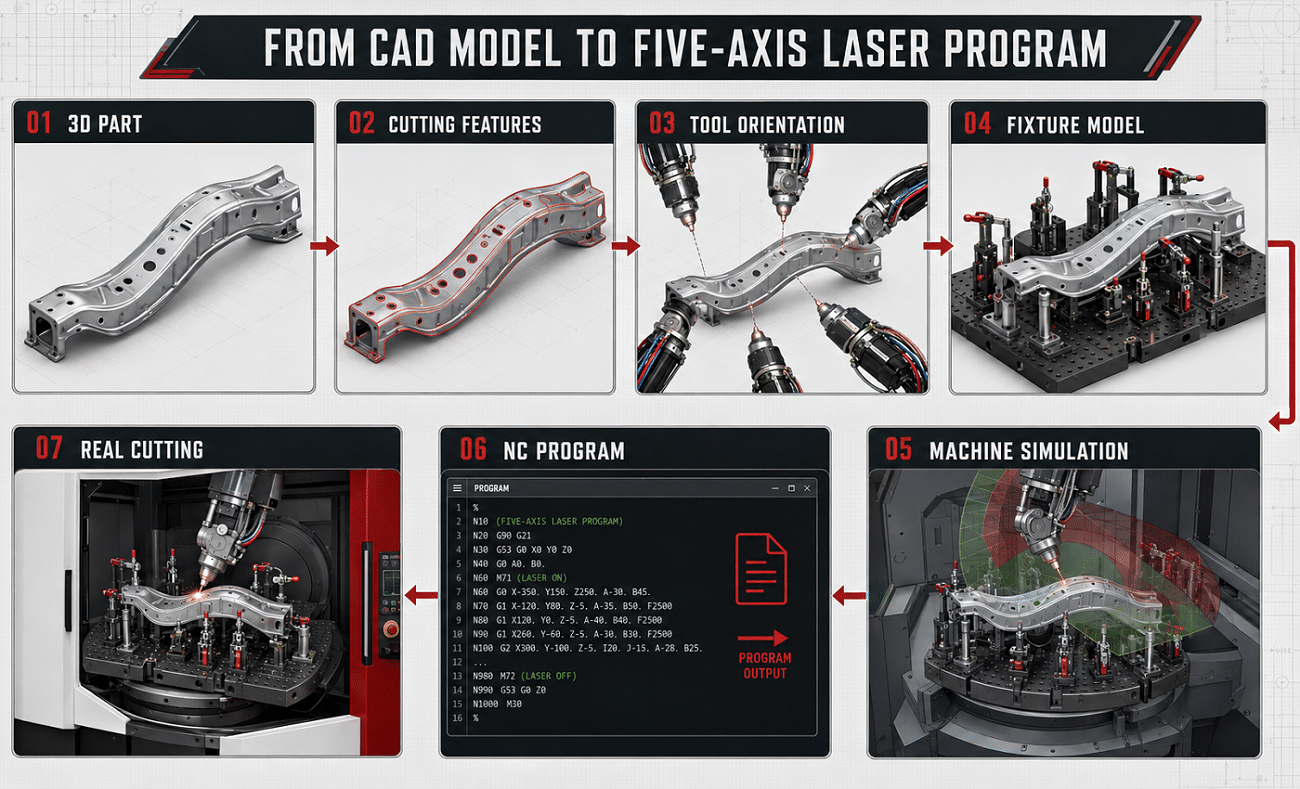
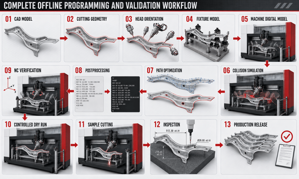
A typical workflow is:
3D CAD Model
→ Define Cutting Geometry
→ Generate Cutting Path
→ Set Cutting-Head Orientation
→ Add Fixture and Machine Model
→ Simulate Five-Axis Motion
→ Check Collisions
→ Optimize Sequence
→ Generate NC Program
→ Transfer to Machine
The biggest production advantage is that programming can happen while the machine continues processing other jobs.
TRUMPF specifically describes this parallel programming as one of the main benefits of 3D offline programming: new programs can be created while production continues rather than occupying the real machine for programming work.
Offline Programming Does Not Mean “Zero Machine Setup”
The software creates the digital production program.
The real machine still requires:
- Correct fixture installation
- Coordinate verification
- Machine calibration
- Correct workpiece
- Correct parameter set
- Controlled first-run verification
Offline programming reduces machine-side engineering time.
It does not remove the need for safe commissioning.
2. Why Five-Axis Laser Cutting Needs More Simulation Than 2D Cutting
In 2D cutting, most movement is easy to predict.
A head moves above a flat sheet.
In five-axis cutting, changing tool orientation changes the space occupied by the entire cutting head.
A programmed point may be reachable by the laser beam but not by the physical cutting head.
For example:
The nozzle may reach a hole correctly.
But when the head tilts 55°, the upper cutting-head body may collide with:
- A flange
- Clamp
- Fixture bracket
- Pneumatic cylinder
This creates an important principle:
Laser accessibility is not the same as cutting-head accessibility.
The complete three-dimensional cutting head must be evaluated.
3. Start With the Correct CAD Model
Every reliable offline program starts with correct geometry.
Before programming, confirm:
- Part revision
- Drawing revision
- Units
- Coordinate orientation
- Finished trim geometry
- Required holes
- Required slots
- Bevel requirements
- Datum references
Wrong Revision = Correct Program for the Wrong Part
This sounds obvious, but engineering revisions are a major practical risk.
A customer may send:
- Original forming model
- Updated production model
- Separate 2D drawing
- Modified trim definition
If the programmer uses an outdated CAD file, collision simulation may be perfect while the actual component is wrong.
Establish Revision Control
The programming record should identify:
- Customer
- Part number
- CAD revision
- Fixture revision
- NC program revision
- Parameter revision
This becomes particularly important when multiple automotive variants share similar fixtures.
4. Separate Part Geometry From Cutting Geometry
The complete CAD model tells the software what the component looks like.
But the programmer must still determine what should actually be cut.
Typical processing geometry includes:
- External trim contours
- Internal openings
- Circular holes
- Slots
- End cuts
- Relief features
- Bevels
Do Not Automatically Convert Every CAD Edge Into a Cutting Path
Some CAD edges may represent:
- Formed transitions
- Surface boundaries
- Construction geometry
- Assembly references
rather than laser-cut contours.
The cutting geometry should therefore be derived from:
- Engineering drawing
- Product requirements
- Customer confirmation
not merely visible CAD edges.
5. Establish the Correct Workpiece Coordinate System
The virtual part must correspond to the real part on the fixture.
Typical coordinate relationships include:
Machine Coordinate System
↓
Fixture Coordinate System
↓
Workpiece Coordinate System
↓
CAD / CAM Program
If this relationship is wrong, the program can be internally correct but applied at the wrong physical location.
Typical symptoms include:
- Entire trim line shifted
- Holes consistently offset
- Program rotated relative to part
- Program works on one fixture but not another
Coordinate setup is therefore part of programming—not merely machine setup.
3D five-axis laser cutting accuracy
6. Import the Fixture Into the Simulation
The workpiece alone is not enough.
The fixture should be represented digitally.
Include:
- Fixture base
- Locating pins
- Supports
- Clamps
- Clamp arms
- Pneumatic cylinders
- Sensors
- Brackets
- Worktable interface
The recently published ZG Laser fixture-design article makes this same point: every locator, support and clamp should be evaluated against the complete cutting-head movement envelope.
Use Realistic Geometry
Do not simplify a pneumatic clamp into a small block if the actual clamp has:
- Tall lever
- Cylinder
- Hose connector
- Mounting bracket
That “unimportant” geometry may become the real collision point.
7. Include the Real Cutting-Head Geometry
Collision simulation should not use only a laser axis line.
The digital head model should include the collision-relevant geometry of:
- Nozzle
- Sensor area
- Lower head
- Main cutting-head body
- Rotary mechanism
- Protective structures
Where relevant, also consider:
- Cable routing
- Optical fiber routing
- Gas lines
The more accurately the digital model represents the real machine, the more useful collision simulation becomes.
This reflects the wider principle used in modern multi-axis CAM simulation: Siemens recommends realistic machine models including kinematics, fixtures and tooling when validating programs and detecting collisions.
8. Cutting-Head Orientation Is a Programming Variable
For each point on a 3D cutting path, the programmer must decide:
From what direction should the laser head approach the surface?
The theoretically simple choice is to align the laser beam with the local surface normal.
But real production may require modifying that orientation.
Reasons include:
- Fixture collision
- Adjacent wall
- Machine travel
- Rotary-axis limit
- Slag direction
- Gas delivery
- Better transition between paths
Tool Orientation Affects More Than Collision
It can influence:
- Kerf geometry
- Taper
- Nozzle clearance
- Gas effectiveness
- Accessibility
- Axis motion
The best orientation is therefore a compromise between:
geometry + cutting process + machine kinematics.
9. Avoid Unnecessary Head Rotation
Five-axis capability does not mean the head should constantly rotate.
Excessive rotary motion may:
- Increase cycle time
- Create unnecessary axis acceleration
- Move toward axis limits
- Produce awkward transitions
- Increase collision risk
Where possible, the programmer should seek smooth orientation changes.
A good five-axis program does not merely reach every point.
It reaches every point efficiently and predictably.
10. Check Rotary-Axis Limits
Every five-axis head has a defined rotary working range.
The program must stay inside it.
A path can therefore be geometrically valid but impossible for the real machine.
Potential issues include:
- Axis reaches positive limit
- Axis reaches negative limit
- Required orientation cannot be achieved
- Head must reverse orientation
- Large unnecessary rotation occurs between features
Simulation should identify these conditions before machine execution.
ZG Laser’s current five-axis equipment positioning explicitly combines offline programming with five-axis control for complex 3D geometries, making machine-specific motion verification an important part of the programming process.
11. Watch for Kinematic Transitions
In simultaneous multi-axis movement, the controller must coordinate several possible axis positions to produce the requested tool orientation.
Certain geometries may create difficult transitions where rotary axes:
- Accelerate rapidly
- Reverse direction
- Approach travel limits
- Make large movements for a small tool-position change
These should be identified during simulation.
Siemens notes that five-axis simulation needs to represent the actual machine kinematics and controller behavior because the kinematic solution used by the controller affects collision risk and real machine movement.
The Visual Path May Look Smooth While the Axes Are Not
This is why inspecting only the laser-point trajectory is insufficient.
Where software allows, review:
- Rotary-axis values
- Axis velocity
- Axis acceleration
- Direction changes
12. Lead-In and Lead-Out Need 3D Clearance
The finished contour itself may be collision-free.
The approach to that contour may not be.
Programming should include:
- Approach movement
- Piercing position
- Lead-in
- Cutting path
- Lead-out
- Retract
Piercing Position Matters
Avoid placing piercing where it can:
- Damage a finished edge
- Leave visible marks
- Direct slag onto a locator
- Interfere with a nearby wall
- Reduce hole quality
Retract Motion Matters Too
After finishing a contour, the cutting head must safely leave the part.
Do not assume the reverse of the approach path is always the best retract path.
13. Collision Checking Must Include Rapid Moves
This is one of the most important programming rules.
The cutting path may be perfectly safe while the rapid movement between two cutting features causes a collision.
For example:
- Head finishes a side-wall hole.
- Laser turns off.
- Machine rapidly moves to another feature.
- Head crosses directly through a tall flange.
Therefore simulate:
- Cutting moves
- Non-cutting moves
- Approach
- Retract
- Feature-to-feature repositioning
- Return-to-safe-position movements
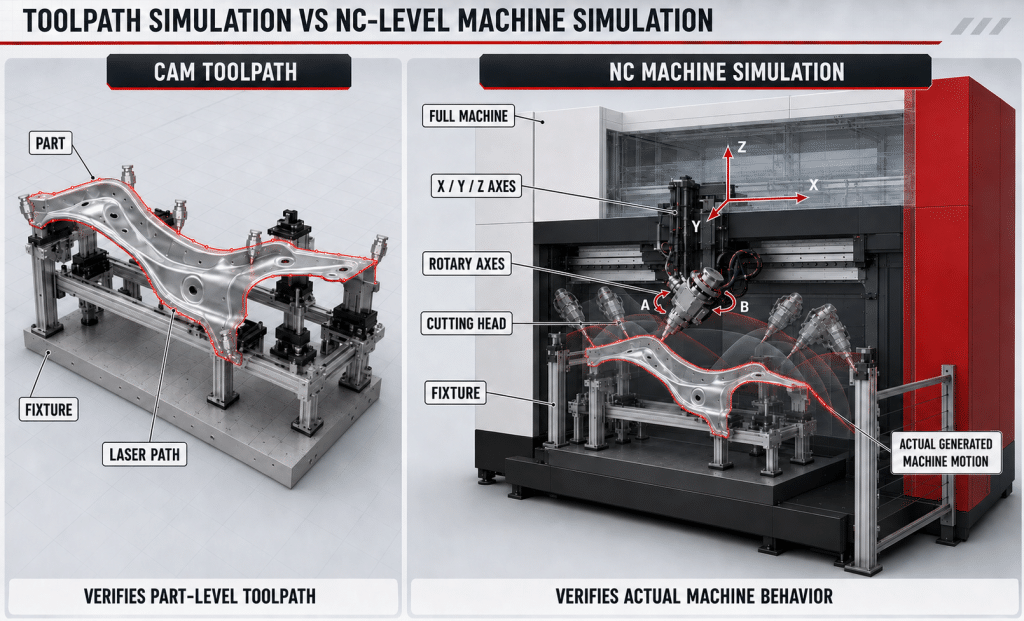
Modern NC-level simulation is valuable specifically because movements introduced after CAM path creation can also be checked. Siemens distinguishes toolpath simulation from G-code-driven simulation and notes that postprocessed NC simulation can include additional machine motions generated by the postprocessor.
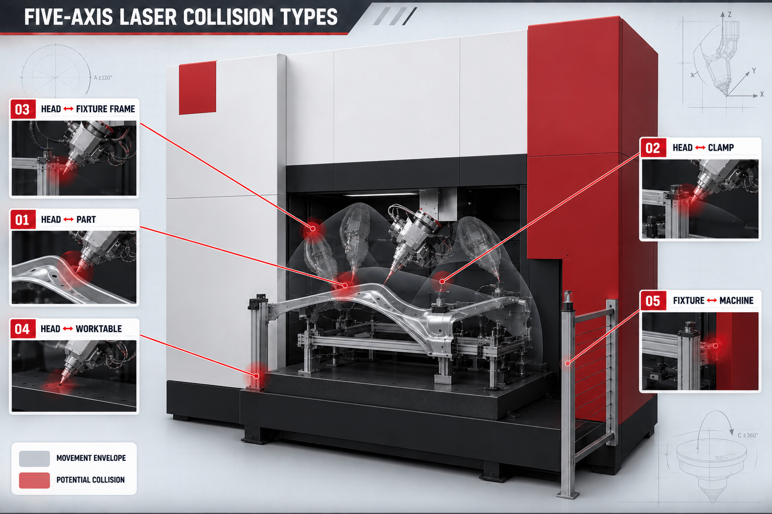
14. What Types of Collision Should Be Checked?
A complete five-axis simulation should evaluate several collision pairs.
Cutting Head vs Workpiece
Especially:
- Deep walls
- Steep flanges
- Recesses
- Narrow openings
Cutting Head vs Fixture
Including:
- Clamps
- Pins
- Supports
- Fixture frame
Cutting Head vs Worktable
Particularly around:
- Low features
- Large head tilt
Head vs Machine Structure
Depending on machine layout:
- Door
- Enclosure
- Gantry
- Internal covers
Fixture vs Machine
Especially when using:
- Rotary tables
- Large fixtures
Workpiece vs Machine
Large parts may extend into restricted areas during table movement.
15. Use a Cutting-Head Swept Envelope
Checking the head at several individual positions is useful but may miss collisions between those positions.
A stronger engineering method is to consider the swept envelope of the head.
This represents the complete volume occupied while the head travels through a movement.
It is particularly useful around:
- Tight clamps
- Deep recesses
- Head rotations
- Corners
- Rapid orientation changes
This concept also connects directly with fixture design.
If the fixture intersects the required swept envelope, the engineering team may need to:
- Move a clamp
- Reduce clamp height
- Change support geometry
- Change cutting-head orientation
- Modify sequence
16. Collision Avoidance Is Not Always Path Avoidance
When simulation finds a collision, the first reaction should not always be:
“Move the cutting path.”
The trim path is usually defined by the part drawing.
Instead, evaluate possible changes in this order:
- Cutting-head orientation
- Approach/retract path
- Cutting sequence
- Clamp position
- Fixture geometry
- Part orientation
- Machine configuration
The finished geometry should only change when engineering allows it.
This is why fixture design and programming should be developed together rather than sequentially.
17. Cutting Sequence Is Part of Offline Programming
The order in which features are processed affects:
- Cycle time
- Heat input
- Scrap release
- Part stability
- Collision risk
A program might include:
- Assembly holes
- Internal slots
- Small openings
- Large trim contour
A Practical Sequence May Prioritize Critical Features
For some formed parts:
- Cut critical holes while the component is fully supported.
- Cut internal openings.
- Cut selected trim sections.
- Complete large external trimming.
This can help prevent the part from losing stiffness too early.
The exact sequence should be verified on real parts.
18. Think About Scrap Before Running the Program
Collision simulation often focuses on the original component.
But the geometry changes during cutting.
A removed slug or trimmed flange may:
- Fall
- Remain partially attached
- Tilt
- Rest on the fixture
- Interfere with the next head movement
Ask After Every Major Cut:
- Where will the removed material go?
- Can it fall freely?
- Can it remain trapped?
- Can it contact the nozzle?
- Could it cover a sensor?
- Can it accumulate in the fixture?
Static CAD simulation may not perfectly predict the behavior of loose scrap.
This is one reason controlled first-part verification remains necessary even after successful digital simulation.
19. Program Around Slag Direction
The cutting-head angle affects where sparks and molten metal travel.
Avoid directing slag toward:
- Fixture datums
- Sensors
- Pneumatic components
- Cables
- Optical protection
- Other finished surfaces
Programming and fixture engineering should therefore consider the direction of material ejection.
Sometimes a small change in:
- Cutting direction
- Start point
- Head orientation
can improve fixture protection.
20. Laser Parameters Belong in the Offline Program
Geometry alone is not enough.
The program may also assign process conditions for different features.
These can include:
- Laser power
- Cutting speed
- Assist gas
- Gas pressure
- Focus
- Nozzle
- Piercing strategy
TRUMPF’s offline programming approach combines geometric programming with integrated processing technology and standard parameters rather than treating them as completely separate workflows.
Different Features May Require Different Parameters
For example:
- Small hole
- Long trim edge
- Angled surface
- Thick local section
may not necessarily use identical process conditions.
21. Simulate Nozzle Accessibility, Not Just Head Clearance
A head may avoid collision but still have poor process geometry.
Examples:
- Nozzle too far from surface
- Nozzle angle causes poor gas delivery
- Recess prevents stable height sensing
- Nearby wall disrupts gas flow
Therefore simulation should ask two separate questions:
Can the head physically reach the feature?
and:
Can the process cut the feature correctly from that orientation?
That distinction is important for:
- Deep side-wall holes
- Sharp recesses
- Angled flanges
- Small internal openings
22. The Machine Model Must Match the Real Machine
Collision simulation depends on the accuracy of the virtual environment.
The model should correspond to the actual:
- Machine version
- Worktable
- Cutting head
- Rotary geometry
- Fixture location
- Optional equipment
Siemens refers to this concept as using a realistic virtual machine or digital twin containing the actual machine kinematics, which improves collision checking and NC program validation.
A Generic Five-Axis Model Is Not Enough
Two five-axis machines may differ in:
- Head size
- Head pivot position
- Axis travel
- Rotary range
- Enclosure geometry
A path safe on one machine may not be safe on another.
23. Understand the Role of the Postprocessor
CAM software creates a toolpath.
The machine controller executes an NC program.
The postprocessor converts the programmed operation into machine-specific NC instructions.
This step may affect:
- Axis commands
- Orientation
- Safe positions
- Machine-specific functions
- Laser on/off commands
- Process macros
For this reason, advanced validation can go beyond the internal CAM trajectory and simulate the postprocessed NC program.
Siemens specifically describes G-code-driven simulation as a way of validating the motion generated from NC output, including content added by the postprocessor.
Practical Purchasing Question
When evaluating software, ask:
Is the simulation based on the CAM path, or can it validate the actual postprocessed machine program?
Both can be useful.
They are not identical.
24. Toolpath Simulation vs NC Program Simulation
This distinction is worth explaining clearly.
Toolpath Simulation
Shows the intended CAM movement.
Useful for:
- Fast programming checks
- Head orientation
- Basic collision detection
- Path optimization
NC / G-Code Simulation
Uses postprocessed machine instructions.
Potentially checks:
- Real axis commands
- Controller-related motion
- Safe-position movements
- Postprocessor output
- Complete machine kinematics
Siemens provides both levels and describes G-code-driven simulation as the higher-fidelity approach for verifying actual CNC execution.
For an industrial five-axis laser project, the buyer should understand what level of verification the supplied programming package actually provides.
25. Simulation Should Also Estimate Cycle Time
Collision avoidance is only one goal.
Offline programming can also help optimize production efficiency.
Compare:
- Cutting distance
- Rapid movement distance
- Number of pierces
- Head orientation changes
- Feature sequence
- Table movements
TRUMPF includes path optimization within its offline programming workflow, while modern virtual-machine solutions can also support production-time estimation before physical production begins.
Reduce Non-Cutting Movement
Instead of:
Feature A
→ long retract
→ major head rotation
→ Feature B
→ opposite side
→ Feature C
a better sequence may group features according to:
- Location
- Head angle
- Surface
- Cutting parameter
The shortest geometric path is not always the fastest path if it requires excessive rotary-axis movement.
26. Do Not Optimize Cycle Time Before Safety
A dangerous path that is two seconds faster is not an optimized path.
Program optimization should normally follow this priority:
- Correct geometry
- Collision safety
- Process quality
- Machine stability
- Cycle time
Once the process is safe and stable, optimize unnecessary motion.
27. Offline Programming Is Especially Valuable for Hot-Formed Parts
Automotive hot-formed components often contain:
- Multiple 3D trim surfaces
- Deep side walls
- Numerous holes
- Tight clamp clearances
- Dedicated fixtures
Typical examples include:
- B-pillars
- Door rings
- Crossmembers
- Roof reinforcements
- Rocker reinforcements
The article already published on ZG Laser’s site describes the same workflow: importing the 3D model, defining the trim path, designing the fixture, establishing coordinates and simulating complete motion before cutting.
Laser trimming of hot-formed automotive parts
28. Offline Programming Does Not Replace Calibration
The virtual system assumes that the real machine corresponds to the digital model.
If the actual machine has:
- Incorrect TCP
- Rotary-axis calibration error
- Shifted cutting head
- Incorrect fixture position
then a perfectly simulated program can still produce an inaccurate part.
Therefore simulation and calibration solve different problems.
Simulation Answers
Can the programmed movement safely and correctly occur?
Calibration Answers
Does the real machine physically execute that movement where the digital model expects?
Both are required.
Five-axis laser cutting calibration and accuracy
29. Validate the Real Fixture Against the Digital Fixture
After fixture manufacturing, compare it with the digital model.
Check:
- Locator position
- Clamp position
- Clamp height
- Fixture orientation
- Worktable location
A fixture may be modified during assembly.
For example:
- Clamp moved 20 mm
- New sensor bracket added
- Hose guide added
If these changes are not updated in the simulation model, future programs may contain hidden collision risks.
Maintain a Digital Fixture Revision
Recommended record:
Fixture ID: BP-01
Digital Model: Rev C
Physical Fixture: Rev C
NC Program: Rev 05
Part CAD: Rev F
Digital and physical configuration should remain synchronized.
30. First-Part Verification Is Still Required
Passing offline collision simulation is not permission to run an unfamiliar program at full speed immediately.
A controlled first-run procedure may include:
- Confirm correct fixture.
- Confirm correct workpiece.
- Confirm NC revision.
- Confirm coordinate system.
- Confirm machine calibration.
- Verify clamps.
- Run controlled laser-off movement where appropriate.
- Reduce feed for critical first movements.
- Observe tight-clearance areas.
- Perform first sample cut.
- Measure critical dimensions.
The exact commissioning procedure should follow the machine manufacturer’s safety and operating requirements.
Why?
Simulation cannot perfectly predict:
- Part-to-part variation
- Flexible scrap
- Unexpected fixture contamination
- Assembly deviations
- Real clamping deformation
Offline programming dramatically reduces risk.
It does not turn physical commissioning into an unnecessary step.
31. Dry Run vs Sample Cut
These two tests answer different questions.
Dry / Laser-Off Verification
Primarily evaluates:
- Motion
- Clearance
- Coordinate setup
- Program sequence
Sample Cutting
Evaluates:
- Cutting quality
- Actual kerf
- Gas delivery
- Heat effects
- Slag behavior
- Finished-part dimensions
Both may be useful for difficult new parts.
32. Common Offline Programming Problems
| Problem | Likely Cause | First Check |
|---|---|---|
| Head collides with clamp | Fixture not modeled accurately | Compare digital and physical fixture |
| Path works in CAM but not machine | Postprocessor or machine model mismatch | Validate NC output |
| Rotary axis reaches limit | Poor head orientation | Re-optimize orientation |
| Excessive axis rotation | Unoptimized kinematic transition | Review axis motion |
| Nozzle reaches part but head collides | Only beam/nozzle was checked | Use full head model |
| Collision during rapid movement | Only cutting path simulated | Simulate non-cutting moves |
| Program shifted on real part | Coordinate mismatch | Fixture/workpiece zero |
| Safe simulation but inaccurate cut | Calibration/TCP issue | Verify machine calibration |
| Slug hits head | Scrap behavior not considered | Review sequence and clearance |
| Gas performance poor on angled feature | Orientation unsuitable | Review head angle and nozzle geometry |
| Cycle time too long | Excessive rapid/head rotation | Optimize sequence |
| Old program used | Weak revision control | Program management system |
33. A Practical Offline Programming Workflow
A robust project can follow this sequence.
Step 1 — Confirm Engineering Data
Collect:
- Part CAD
- Drawing
- Revision
- Material
- Thickness
- Required tolerance
Step 2 — Define Cutting Features
Select:
- Trims
- Holes
- Slots
- Bevels
Step 3 — Establish Datums
Match the CAD coordinate system with the fixture strategy.
Step 4 — Create Initial Cutting Paths
Set:
- Direction
- Pierce
- Lead-in
- Lead-out
Step 5 — Define Head Orientation
Balance:
- Surface relationship
- Accessibility
- Gas delivery
- Machine limits
Step 6 — Import Fixture Model
Include all relevant geometry.
Step 7 — Load Correct Machine Model
Include the actual:
- Head
- Worktable
- Axis geometry
Step 8 — Run Collision Simulation
Check:
- Cutting
- Approach
- Retract
- Rapid movement
- Axis limits
Step 9 — Optimize Sequence
Reduce:
- Empty travel
- Unnecessary head rotation
- Repeated orientation changes
Step 10 — Assign Process Parameters
Define appropriate:
- Power
- Gas
- Speed
- Focus
- Piercing
Step 11 — Generate NC Program
Use the correct machine-specific postprocessor.
Step 12 — Validate NC Output
Where supported, run full machine / NC simulation.
Step 13 — Transfer With Revision Control
Verify correct:
- Part
- Fixture
- Program
Step 14 — Controlled First Run
Verify real-world movement.
Step 15 — Sample Cutting and Inspection
Measure:
- Critical holes
- Trim position
- Edge quality
- Cycle time
Step 16 — Feed Changes Back Into Offline Program
The final production program should incorporate validated corrections.
34. Program Revision Control Is Essential in Production
Once production starts, the program becomes a controlled manufacturing asset.
Do not save files as:
Bpillar-final.nc
Bpillar-final2.nc
Bpillar-new-final.nc
Bpillar-really-final.nc
Use a structured system.
For example:
Part: BP-RH
Part Revision: F
Fixture: BP-RH-02 Rev C
Program: BP-RH-F-P07
Parameter Set: PHS15-04
Released: 2026-08-xx
Record why revisions changed.
Examples:
- New customer drawing
- Fixture modification
- Parameter optimization
- Cycle-time improvement
- Collision clearance improvement
This reduces the risk of producing the correct part with the wrong revision.
35. What Should Be Included in a Digital Project Package?
For repeated production, retain:
Engineering
- 3D CAD
- 2D drawing
- Revision
Fixture
- Fixture model
- Fixture drawing
- Datum definition
Programming
- CAM project
- NC program
- Postprocessor version
Process
- Parameter tables
- Gas
- Nozzle
- Focus
Validation
- Simulation result
- Sample report
- Dimensional report
The goal is to make the process reproducible rather than dependent on one programmer’s memory.
36. What Should Buyers Ask About Offline Programming Software?
When purchasing a five-axis machine, do not accept:
“Software included.”
Ask what that actually means.
CAD
- Which 3D formats can be imported?
- Can CAD geometry be repaired?
- Can fixture geometry be imported?
Programming
- Can the software generate 3D cutting paths?
- Can head orientation be manually adjusted?
- Can lead-in and lead-out be edited?
- Can different process parameters be assigned?
Simulation
- Does collision checking include the whole head?
- Does it include the fixture?
- Does it include the machine?
- Does it check axis limits?
- Does it simulate rapid moves?
NC
- Is a machine-specific postprocessor included?
- Can the posted NC program be simulated?
- How are program revisions managed?
Production
- Can cycle time be estimated?
- Can the program be edited later?
- Is training included?
- Is software licensing permanent or subscription-based?
- What software support is available?
Not every software package provides the same level of functionality.
TRUMPF’s current solution, for example, combines CAD import, device/fixture work, programming, optimization and collision checking in one 3D laser workflow; that is useful as a benchmark for understanding what a mature offline-programming workflow can contain.
37. How Offline Programming Affects Machine Selection
Software should be evaluated alongside the mechanical machine.
Imagine two machines with similar:
- Axis travel
- Laser power
- Positioning accuracy
but very different programming environments.
Machine A allows:
- Complete 3D simulation
- Fixture import
- Collision checks
- Head-orientation control
- Machine-specific postprocessing
Machine B requires most complex adjustment directly at the machine.
For high-mix 3D production, the software difference can significantly affect:
- Engineering hours
- Changeover time
- Collision risk
- Operator dependence
Therefore:
The programming environment is part of the five-axis machine capability.
38. Offline Programming for Prototype vs Mass Production
The priorities change with production type.
Prototype / Small Batch
Important factors:
- Fast CAD import
- Easy path creation
- Flexible editing
- Short engineering lead time
Mass Production
Important factors:
- Stable validated program
- Revision control
- Cycle-time optimization
- Repeatability
- Digital fixture management
- Controlled change process
The same software may serve both, but the production workflow should be different.
39. Offline Programming for Five-Axis Machines vs Robots
Both use 3D offline programming, but the kinematics are different.
Dedicated Five-Axis Machine
Simulation focuses on:
- Linear axes
- Rotary head
- Machine envelope
- Fixture
Robot
Simulation must additionally consider:
- Robot joints
- Elbow posture
- Wrist configuration
- Robot singularities
- External positioners
- Robot reach
The programming philosophy is related, but the motion platform creates different risks.
40. Final Offline Programming Checklist
Before releasing a program, confirm:
- Correct CAD revision
- Correct drawing revision
- Units confirmed
- Workpiece coordinates confirmed
- Correct fixture revision loaded
- Real clamp geometry included
- Correct machine model loaded
- Correct cutting-head model loaded
- Trim paths verified
- Holes and slots verified
- Cutting direction confirmed
- Piercing locations confirmed
- Lead-ins checked
- Lead-outs checked
- Head orientation optimized
- Nozzle accessibility checked
- Rotary-axis limits checked
- Cutting moves simulated
- Rapid moves simulated
- Full head clearance checked
- Fixture clearance checked
- Worktable clearance checked
- Machine enclosure clearance checked
- Scrap release considered
- Slag direction considered
- Cutting sequence optimized
- Process parameters assigned
- Postprocessor confirmed
- NC output verified
- Cycle time reviewed
- Program revision recorded
- Controlled first-run procedure prepared
- Sample inspection plan prepared
Conclusion
Offline programming is not simply a convenient way to create a five-axis laser cutting path.
It is part of the engineering process that connects:
CAD geometry → fixture → machine kinematics → laser process → real production.
A reliable offline program should answer five questions:
- Is the geometry correct?
- Can the cutting head reach every feature?
- Can the real machine execute the required motion?
- Can it do so without collision?
- Can it do so efficiently and repeatedly?
This is why collision simulation should include much more than the laser line.
It should represent:
- The real part
- The complete cutting head
- Fixture
- Worktable
- Machine structure
- Rotary-axis motion
- Approach and retract
- Rapid movements
And where high-level verification is required, validating the postprocessed machine program with a realistic machine model provides another layer beyond basic CAM path visualization. This same distinction between toolpath checking and NC-driven digital-machine simulation is emphasized by modern multi-axis manufacturing systems.
Most importantly:
A collision-free simulation reduces risk, but it does not eliminate controlled real-machine validation.
The strongest production workflow combines:
offline programming + accurate fixture model + machine simulation + calibration + controlled first run + sample inspection
before production release.
Evaluate Your 3D Part Before Programming the Production Cell
Send ZG Laser:
- 3D CAD model
- 2D drawing
- Material
- Thickness
- Required trim paths
- Critical tolerances
- Annual production volume
- Target cycle time
- Fixture requirements
Our application team can evaluate:
- Cutting-head accessibility
- Fixture clearance
- Five-axis working range
- Cutting orientation
- Collision risks
- Offline-programming strategy
- Sample-validation requirements
before final production configuration.
Frequently Asked Questions
What is offline programming in five-axis laser cutting?
Offline programming means creating and verifying the 3D cutting program on a separate computer rather than developing the entire program directly at the machine. It can include CAD import, toolpath generation, head orientation, fixture modeling, simulation and NC generation.
Why is collision simulation important for five-axis laser cutting?
The cutting head changes orientation around three-dimensional components. A path that is reachable by the laser beam may still cause the cutting-head body to collide with the workpiece, fixture or machine.
What should be included in a collision simulation?
A useful simulation should include the workpiece, complete cutting head, fixture, clamps, worktable and relevant machine structure. Cutting moves, rapid moves, approaches and retracts should all be evaluated.
Is toolpath simulation the same as NC program simulation?
No. Toolpath simulation normally verifies the CAM-generated movement. NC or G-code simulation uses the postprocessed machine program and can more closely represent the instructions that the machine controller will execute. Siemens distinguishes these levels in its current machine-simulation solutions.
Can collision simulation guarantee that a crash will never happen?
No. Simulation reduces risk, but its accuracy depends on the digital models, coordinate setup, postprocessor and real machine condition. Physical fixture changes, part variation and loose scrap can also create conditions not perfectly represented virtually.
Should the fixture be modeled in the programming software?
Yes. Clamps, locators and supports are common collision risks and should be represented as accurately as practical.
Why do rapid movements need simulation?
A program can have a collision-free cutting path but collide while repositioning between two features. Non-cutting movement should therefore be included in verification.
Does offline programming improve cycle time?
It can. The programmer can optimize cutting sequence, rapid movements and cutting-head orientation before production. TRUMPF specifically includes collision checking and path optimization in its offline 3D programming workflow.
Can offline programming replace a machine dry run?
It should not be treated as a universal replacement for controlled first-program verification. A real machine may differ from the digital environment due to calibration, fixture changes, part variation or other physical conditions.
Why is the postprocessor important?
The postprocessor converts CAM operations into machine-specific NC instructions. Incorrect postprocessing can create motion different from the intended CAM path.
Does offline programming affect cutting accuracy?
Yes. Incorrect coordinates, head orientation, geometry or program revision can create systematic cutting errors even when the machine itself is mechanically accurate.
Can the same offline program be used on different five-axis machines?
Not automatically. Machines may use different kinematics, rotary-axis ranges, cutting heads, controllers and postprocessors. The program should be configured and validated for the specific machine.