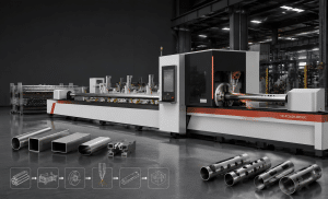
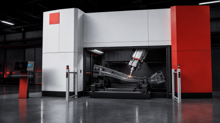
Hot-formed automotive parts combine complex three-dimensional geometry with high material strength. After forming and hardening, many components still require final trimming, hole cutting, slotting or contour correction before they can enter welding and body-in-white assembly.
Conventional flatbed laser cutting machines are designed for two-dimensional sheet metal and cannot maintain the required cutting-head orientation around a formed component. A three-dimensional five-axis laser cutting system controls both the position and angle of the cutting head, enabling it to follow curved surfaces and approach the part from different directions.
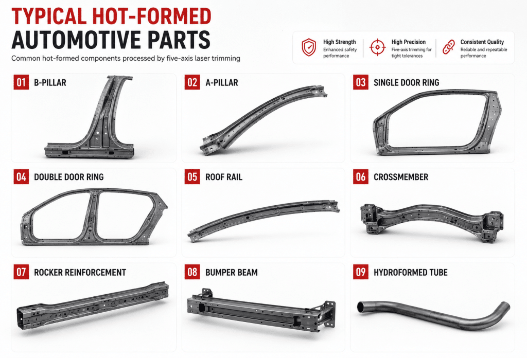
Typical laser-trimmed components include B-pillars, door rings, roof and floor reinforcements, bumper beams, crossmembers and other press-hardened structural parts. Press-hardened steels are commonly used in these safety-related automotive structures because they combine high strength with the ability to produce complex shapes.
This guide explains:
- What hot-formed automotive parts are
- Why final trimming is required
- How five-axis laser trimming works
- Which components are commonly processed
- How fixtures and offline programming affect the result
- How to evaluate accuracy and cycle time
- How five-axis machines compare with robotic cutting systems
- What information is required before selecting equipment
What laser cutting is and how the process works
1. What Is a Hot-Formed Automotive Part?
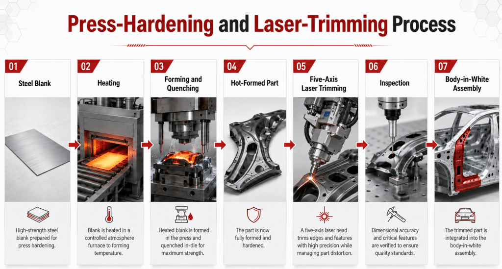
Hot forming, also known as press hardening or hot stamping, is a manufacturing process used to produce strong, lightweight automotive structural components.
In a typical press-hardening process, a suitable steel blank is heated, formed inside a press and cooled under controlled conditions. The forming and quenching process transforms the material into an ultra-high-strength component while allowing complex shapes to be produced with good dimensional stability.
Press-hardened components are frequently used in areas of a vehicle where intrusion resistance and crash performance are critical, including:
- B-pillar reinforcements
- Windscreen or A-pillar reinforcements
- Door reinforcements
- Front and rear bumper beams
- Floor and roof reinforcements
- Roof and dashboard crossmembers
- Side-impact structures
Hot-Formed, Hot-Stamped and Press-Hardened
These terms are often used in related contexts:
- Hot forming describes forming a material at elevated temperature.
- Hot stamping is commonly used in automotive manufacturing.
- Press hardening emphasizes that the component is formed and hardened in the press.
- Press-hardened steel, or PHS, describes the resulting material category.
The exact production route, material grade and coating may differ between projects, so the cutting process should be evaluated using the actual formed part.
2. Why Do Hot-Formed Parts Require Final Trimming?
The forming process creates the main three-dimensional shape of the component, but the finished part may still require:
- Removal of excess flange material
- Final external contours
- Mounting holes
- Slots
- Locating features
- Welding access features
- Assembly openings
- Variant-specific cutouts
- Correction of forming allowances
The final trim line often lies on a curved or angled surface. Some holes may be located on side walls or recessed areas that cannot be reached from a single vertical direction.
Why Not Cut Every Feature Before Forming?
Certain blank contours and preliminary features can be created before forming. However, not every final feature can be accurately completed at the flat-blank stage.
During forming, the material may experience:
- Stretching
- Compression
- Wall movement
- Springback
- Local deformation
- Changes in feature position
For critical assembly features, final cutting after forming allows the contour and hole positions to be referenced to the finished three-dimensional geometry.
Why Not Use a Conventional Trimming Die?
Mechanical trimming dies can be effective for stable, high-volume production, but they also require dedicated tooling.
A trimming die may involve:
- Tool design and manufacturing
- Tryout and adjustment
- Tool maintenance
- Wear management
- Storage space
- Modification when the part design changes
Laser trimming uses a programmable cutting path instead of a dedicated cutting edge. This can provide greater flexibility for design changes, multiple product variants, prototype production and projects where the cost or lead time of hard tooling is difficult to justify.
This does not mean laser cutting always replaces trimming dies. The correct choice depends on:
- Annual production volume
- Required cycle time
- Number of variants
- Design-change frequency
- Tooling cost
- Part geometry
- Required edge condition
- Available automation
Laser Trimming vs Mechanical Trimming
| Evaluation Factor | Five-Axis Laser Trimming | Mechanical Trimming Die |
|---|---|---|
| Cutting tool | Programmable laser path | Dedicated physical tooling |
| Design changes | Mainly program and fixture changes | Tool modification may be required |
| Multiple variants | Flexible with suitable programming and fixtures | Separate or adjustable tooling may be needed |
| Initial tooling | Fixture and process development | Trimming die development |
| Contact force | Non-contact process | Mechanical cutting force |
| Tool wear | No conventional cutting edge | Cutting edges require maintenance |
| Cycle time | Application-dependent | Can be highly productive in stable mass production |
| Suitable decision basis | Part mix, flexibility and total cost | Stable design and high repetitive volume |
3. Which Automotive Parts Are Commonly Laser Trimmed?
Press-hardened materials are used across a wide range of body-in-white structural and safety components.
B-Pillars
The B-pillar is positioned between the front and rear side doors and plays an important role in side-impact protection.
A formed B-pillar may require:
- External contour trimming
- Mounting holes
- Slots
- Joining features
- Reference holes
- Openings on several surfaces
TRUMPF specifically presents B-pillars as an example of a three-dimensional hot-formed component processed with dedicated laser cutting equipment.
A-Pillars and Windscreen Reinforcements
A-pillar structures can include curved profiles, transitions and features positioned at different angles. The cutting head must maintain sufficient access while avoiding the fixture and adjacent part surfaces.
Door Rings
A door ring integrates structural areas around the side-door opening. Modern press-hardening strategies increasingly include large and integrated single- or double-door-ring components.
Because of their large size and complex geometry, door rings may require:
- Large machine travel
- Multiple cutting orientations
- Carefully planned fixture support
- Collision simulation
- Efficient loading
- Multiple trim paths and internal openings
Crossmembers and Reinforcements
Typical examples include:
- Roof crossmembers
- Dashboard crossmembers
- Seat crossmembers
- Floor reinforcements
- Tunnel reinforcements
- Rocker or sill reinforcements
Bumper Beams
Bumper and anti-intrusion structures may require final length trimming, holes, slots or end profiles after forming.
Hydroformed Tubes
Hydroformed tubes and curved profiles may require:
- Three-dimensional end cutting
- Openings around several faces
- Connection slots
- Assembly features
- Angled contours
A tube laser designed for straight raw profiles may not be suitable once the tube has already been bent or hydroformed into a three-dimensional shape.
Large Integrated Components
Automotive production is moving toward larger, more integrated structural parts in certain applications. As component size and geometric complexity increase, machine travel, fixture design, loading accessibility and automation become increasingly important.
4. How Does Five-Axis Laser Trimming Work?
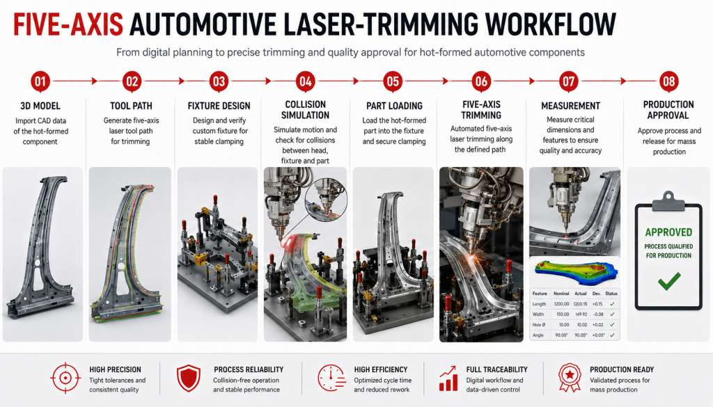
A five-axis laser cutting machine coordinates linear movement and cutting-head orientation to follow a three-dimensional trimming path.
A typical process includes the following stages.
Step 1: Import the Three-Dimensional Model
The engineering team imports the part model into compatible CAD or CAM software.
The model should represent:
- Final formed geometry
- Required trim lines
- Holes and slots
- Critical datums
- Fixture contact areas
- Areas that must remain unmarked
- Joining and assembly features
Step 2: Define the Cutting Path
The programmer establishes:
- Trim-line geometry
- Cutting direction
- Piercing positions
- Lead-in and lead-out paths
- Cutting sequence
- Cutting-head angle
- Nozzle-to-part distance
- Feature priorities
The sequence should consider heat distribution, part stability and the possibility that removing one section may release residual stress.
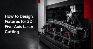
Step 3: Design the Fixture
The fixture locates, supports and clamps the formed part.
Its design must allow the cutting head to reach every required feature without colliding with:
- Clamps
- Support blocks
- Locating pins
- Fixture frames
- Pneumatic components
- The worktable
Step 4: Establish the Coordinate System
The machine program, fixture and workpiece must share a consistent coordinate reference.
Depending on the configuration, setup may involve:
- Fixture reference points
- Machine reference points
- Part datums
- Probing or sensing
- Manual verification
- Program offsets
Step 5: Simulate the Complete Motion
Before cutting, the programmer should simulate:
- Linear-axis travel
- Rotary-axis motion
- Cutting-head orientation
- Lead-in movement
- Fixture clearance
- Machine-limit conditions
- Cable or optical-fiber movement
- Part accessibility
Step 6: Load and Clamp the Part
The operator or automation system loads the component into the fixture.
The part should contact the intended locating points without excessive force or deformation.
Step 7: Pierce and Trim
The machine performs the programmed operations, which may include:
- Piercing
- Outer contour trimming
- Hole cutting
- Slot cutting
- End cutting
- Selected bevel or angled cuts
Step 8: Unload and Inspect
After cutting, the component is removed and inspected against the agreed criteria.
The result may be checked using:
- Gauges
- Calipers
- Checking fixtures
- Coordinate measuring machines
- 3D scanning
- Vision systems
5. Why Is a Five-Axis Machine Required?
A standard flatbed cutting machine normally moves the cutting head over a flat sheet.
Hot-formed components require the laser head to approach:
- Curved surfaces
- Side walls
- Angled flanges
- Recessed openings
- Multiple faces
- Changing surface normals
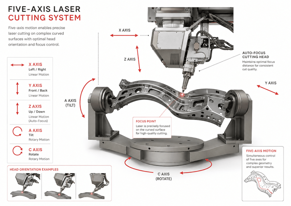
A five-axis system combines linear movement with rotary movement so that the cutting head can maintain the required position and orientation along the path.
Linear Axes
The X, Y and Z axes position the cutting head within the working envelope.
They determine whether the system can reach:
- The complete component
- Both ends of a large part
- High and low surfaces
- Features located around the fixture
Rotary Axes
The rotary axes change the angle of the cutting head.
They allow the head to:
- Follow curved surfaces
- Cut angled features
- Maintain suitable nozzle orientation
- Reach side-wall contours
- Avoid nearby part geometry
ZG Laser’s current five-axis product portfolio is designed around formed and irregular three-dimensional components and includes different working envelopes, worktable arrangements and laser-power options.
Tool Center Point Control
When the cutting head rotates, the control system must maintain the programmed location of the focused laser relative to the part.
Calibration errors can create:
- Trim-line offsets
- Hole-position errors
- Incorrect cutting angles
- Changes between different head orientations
Accessibility Matters as Much as Machine Travel
A machine may have sufficient nominal X, Y and Z travel but still be unable to cut a feature because:
- The cutting head body is too large
- The nozzle cannot reach a recessed area
- The fixture blocks the approach path
- A rotary axis reaches its limit
- The machine enclosure restricts motion
- The part creates a collision risk
For this reason, the actual 3D model and fixture concept should be evaluated before machine selection.
6. Five-Axis Machine vs Robotic Laser Cutting
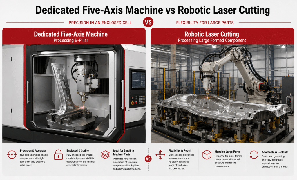
Both dedicated five-axis machines and industrial robots can process three-dimensional parts, but they use different motion structures.
| Factor | Dedicated Five-Axis Machine | Robotic Laser Cutting System |
|---|---|---|
| Motion structure | Machine-tool linear and rotary axes | Multi-joint industrial robot |
| Working envelope | Defined machine enclosure | Flexible robot reach |
| Programming | 3D CAM and machine control | Robot programming and simulation |
| Fixture | Dedicated fixture or production table | Fixture or external positioner |
| Typical strength | Controlled repetitive production | Flexible geometry and large reach |
| Part changes | Program and fixture dependent | Flexible when cell is properly designed |
| Automation | Can use rotary tables and loading systems | Can integrate robots, positioners and conveyors |
| Evaluation focus | Accuracy, accessibility, cycle time | Reach, posture, calibration and flexibility |
A Five-Axis Machine May Be Preferred When:
- The production requires a machine-tool-style platform
- The part fits within a defined working envelope
- Repeat production is important
- Rotary-table loading is required
- The production cell is dedicated to formed components
- Integrated enclosure and process control are priorities
A Robotic System May Be Preferred When:
- Parts are large or vary significantly
- A large flexible reach is needed
- The robot performs several orientations or operations
- Production volume is lower or product variety is high
- An external positioner can improve accessibility
- The factory already uses robotic manufacturing cells
Neither solution should be selected solely from a general claim about accuracy or flexibility. The customer should compare them using the actual part, tolerance, fixture, production volume and target cycle time.
7. Fixture Design for Hot-Formed Components
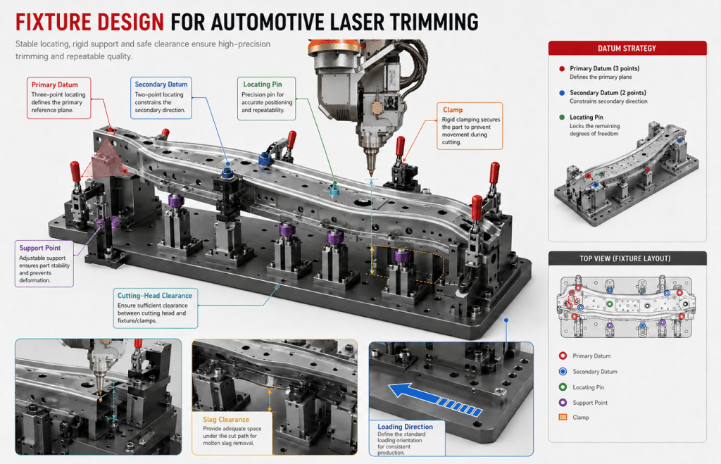
The fixture is part of the cutting system, not merely an accessory.
A machine with good axis performance cannot produce consistent parts when the workpiece is incorrectly located or deformed during clamping.
Datum Selection
The fixture should reference stable features that represent the engineering datum strategy.
Possible references include:
- Formed surfaces
- Existing holes
- Edges
- Locating pads
- Functional assembly datums
Features with high forming variation should not be used as primary locating points without careful evaluation.
Part Support
The fixture should provide enough support to prevent:
- Movement during cutting
- Vibration
- Local bending
- Sagging
- Rotation
- Instability after the trim line is released
At the same time, excessive support may obstruct the cutting head or trap slag.
Clamping Force
Clamps should secure the part without forcing it into an artificial shape.
Excessive clamping force may:
- Distort a thin flange
- Change hole position
- Hide forming variation
- Create dimensional changes after unclamping
Cutting-Head Access
Fixture components should remain outside the required approach envelope.
The design should account for:
- Nozzle length
- Cutting-head diameter
- Rotary movement
- Lead-in paths
- Piercing position
- Slag direction
- Collision clearance
Slag and Fume Management
The fixture should allow molten material, sparks and smoke to move away from:
- Locating surfaces
- Pneumatic cylinders
- Sensors
- Cables
- Precision components
Replaceable protection plates may be useful in areas exposed to repeated cutting.
Loading and Unloading
The fixture should support the planned production method:
- Manual loading
- Two-hand loading
- Robot loading
- Rotary-table loading
- Multi-station production
Ergonomics and accessibility can affect the real cycle time as much as cutting speed.
Quick-Change Fixtures
When several component variants are produced, consider:
- Standard fixture bases
- Locating pins
- Repeatable mounting interfaces
- Quick pneumatic connections
- Fixture identification
- Program interlocks
- Stored coordinate systems
8. Offline Programming and Collision Simulation
Three-dimensional trimming programs should normally be prepared and verified before they are run on the machine.
3D Model Preparation
The programmer should confirm:
- Correct model revision
- Correct units
- Complete trim geometry
- Accurate part orientation
- Fixture model availability
- Machine model availability
- Required quality features
Cutting-Head Orientation
The software must determine how the head approaches each section of the cutting path.
The orientation should provide:
- Sufficient clearance
- Stable gas delivery
- Suitable cutting angle
- Controlled cable and fiber movement
- Smooth rotary-axis motion
Lead-In and Lead-Out
Piercing and entry positions should be selected to avoid:
- Critical finished surfaces
- Visible edge defects
- Excessive local heat
- Collision with nearby walls
- Slag contamination of fixture datums
Collision Simulation
Simulation should include more than the theoretical laser path.
The virtual environment should represent:
- Cutting head
- Nozzle
- Part
- Fixture
- Clamps
- Worktable
- Machine enclosure
- Rotary-axis limits
- Relevant cables or protective structures
Program Verification
The first run should use a controlled commissioning procedure.
Depending on the machine and software, verification may include:
- Reduced-speed dry run
- Laser-off trajectory check
- Increased clearance
- Step-by-step execution
- Operator observation
- Controlled first-part cutting
Not every software package or machine configuration includes the same simulation and programming functions. The specific software, licenses, post-processors and training scope should be confirmed in the quotation.
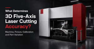
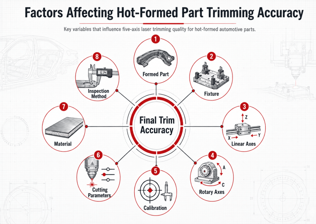
9. What Determines Final Cutting Accuracy?
Final part accuracy is the result of the complete production system.
It is not the same as the positioning-accuracy figure listed on a machine specification sheet.
Important factors include:
Machine Accuracy
- Linear-axis positioning
- Repeat positioning
- Rotary-axis performance
- Servo control
- Mechanical condition
- Thermal stability
Cutting-Head Calibration
- Focus position
- Nozzle centering
- Height sensing
- Rotary-axis calibration
- Tool-center-point calibration
Fixture Repeatability
- Fixture mounting
- Locating-pin condition
- Support-point wear
- Clamp consistency
- Contamination on datums
Part Variation
Hot-formed components may vary because of:
- Blank variation
- Heating conditions
- Forming conditions
- Cooling conditions
- Coating behavior
- Material springback
- Tool wear
Process Parameters
- Laser power
- Cutting speed
- Focus
- Assist gas
- Gas pressure
- Nozzle
- Piercing strategy
- Kerf compensation
Inspection Method
A part may produce different measurement results depending on whether it is inspected:
- Free-state
- Clamped
- On a checking fixture
- Using a CMM
- Using a 3D scanner
The acceptance method should therefore be agreed before sample testing.
Dimensional Stack-Up
A trim-line error may result from the combined effect of several small variations:
Final Part Variation = Formed-Part Variation + Fixture Variation + Machine Variation + Calibration Variation + Process Variation
The formula is conceptual rather than a simple arithmetic tolerance calculation. Each project should establish its own measurement and capability plan.
10. How Should Laser Power Be Selected?
Laser power should be selected according to the real part and production requirement.
Important inputs include:
- Material grade
- Coating
- Material thickness
- Required cutting speed
- Piercing requirements
- Hole sizes
- Edge-quality standard
- Assist gas
- Part accessibility
- Target cycle time
- Production volume
Do Not Select Power by Thickness Alone
Two projects with the same nominal material thickness may require different configurations because of:
- Different material grades
- Different coatings
- Different hole quantities
- Different contour lengths
- Different quality criteria
- Different required cycle times
- Different cutting-head angles
Evaluate Typical Production
The most frequently processed parts should have the greatest influence on machine power.
A configuration should not be selected only for the thickest part that may be processed occasionally.
Conduct Real Sample Tests
The supplier should test:
- Actual material
- Actual formed geometry
- Actual trim paths
- Representative holes
- Representative cutting angles
- Required cycle-time conditions
ZG Laser’s current five-axis brochure presents multiple equipment platforms and different laser-power options, but the final configuration should be confirmed through part evaluation and sample testing rather than a universal thickness chart.
11. Assist Gas and Edge Requirements
Assist gas removes molten material from the cutting kerf and influences edge appearance, oxidation, dross and process stability.
Nitrogen
Nitrogen may be selected when a low-oxidation edge is important.
It can be relevant when the component will proceed to:
- Welding
- Adhesive bonding
- Coating
- Corrosion-protection processes
- Visible assembly
Gas consumption and pressure requirements should be included in the operating-cost calculation.
Oxygen
Oxygen may support the cutting reaction on suitable steels, but it produces an oxidized edge.
The customer should determine whether the oxide layer affects:
- Welding
- Coating
- Adhesion
- Corrosion protection
- Final appearance
Compressed Air
Compressed air may be considered in suitable applications, but the result depends on:
- Pressure
- Flow
- Moisture
- Oil filtration
- Material
- Thickness
- Edge requirement
The process should be validated on actual parts.
Gas Delivery on Angled Surfaces
Three-dimensional cutting places additional demands on:
- Nozzle alignment
- Nozzle-to-part distance
- Head angle
- Gas flow into the kerf
- Accessibility around flanges
- Slag direction
A parameter that works on a flat test coupon may not produce the same result on an angled or recessed feature.
12. How Should Cycle Time Be Evaluated?
The cutting time displayed by the CNC is only one part of the production cycle.
A complete cycle can include:
- Part loading
- Part positioning
- Fixture clamping
- Part or fixture confirmation
- Machine-table movement
- Piercing
- Outer contour cutting
- Hole and slot cutting
- Cutting-head repositioning
- Unclamping
- Part unloading
- Fixture cleaning
- Inspection or sampling
A practical cycle-time formula is:
Total Cycle Time = Loading + Positioning + Clamping + Cutting + Table Movement + Unclamping + Unloading
Factors That Can Create Cycle-Time Variation
- Inconsistent manual loading
- Part-form variation
- Fixture contamination
- Piercing instability
- Frequent alarms
- Nozzle contamination
- Unplanned program corrections
- Difficulty removing cut scrap
- Slow part inspection
- Fixture changeover
Evaluate Repeated Cycles
One successful demonstration is not enough.
Where possible, the supplier should process several consecutive parts and record:
- Total cycle time
- Laser-on time
- Loading time
- Alarm events
- Consumable condition
- Dimensional results
- Operator intervention
Automation of loading and unloading can improve production consistency when the part, fixture and cell are designed for it. Research and industrial systems for five-axis hot-forming applications increasingly evaluate the laser machine as part of an automated production cell rather than as an isolated cutting unit.
13. Fixed Table vs Rotary Table
The worktable configuration should be selected according to part size, fixture design, production volume and loading strategy.
Fixed Table
A fixed table may be appropriate for:
- Large components
- Prototype production
- Low- or medium-volume projects
- Flexible fixture arrangements
- Long parts
- Projects where table rotation provides limited benefit
Potential advantages include straightforward loading and fewer table-motion requirements.
Rotary Table
A rotary or alternating table may be appropriate for:
- Higher production volume
- Multi-station fixtures
- Alternating loading and cutting
- Reduced machine waiting time
- Semi-automatic production
- Robotic loading
- Dedicated production cells
While one station is inside the cutting area, another station may be used for unloading and loading.
The Table Alone Does Not Determine Productivity
A rotary table will not improve total output when:
- The operator cannot load quickly enough
- Fixture clamping is slow
- Part inspection becomes a bottleneck
- Cut scrap is difficult to remove
- Upstream parts do not arrive consistently
- Downstream assembly cannot accept the output
The complete manufacturing flow should be evaluated.
14. How Is the Finished Part Inspected?
Inspection requirements should be defined before the sample test.
Trim-Line Dimensions
Check:
- Overall contour
- Distance from datum points
- Flange width
- End position
- Profile transitions
Holes and Slots
Check:
- Diameter
- Length and width
- Position
- Orientation
- Edge condition
- Feature-to-feature distance
Cutting Edge
Inspect for:
- Dross
- Incomplete cutting
- Oxidation
- Taper
- Roughness
- Local overheating
- Sharp projections
Part Form
Check whether the trimming process or clamping has affected:
- Overall geometry
- Flange position
- Part twist
- Local deformation
- Assembly fit
Repeatability
Measure several parts to distinguish between:
- One-part accuracy
- Fixture repeatability
- Process stability
- Formed-part variation
- Long-term production capability
Inspection Equipment
Possible tools include:
- Calipers
- Height gauges
- Go/no-go gauges
- Checking fixtures
- Coordinate measuring machines
- 3D scanners
- Vision measurement systems
15. Common Laser-Trimming Problems
| Problem | Possible Causes | Evaluation Direction |
|---|---|---|
| Trim-line offset | Incorrect coordinate system, fixture movement or calibration error | Verify datums, offsets and fixture mounting |
| Inconsistent hole position | Part variation or fixture repeatability | Measure formed parts and inspect locating points |
| Cutting-head collision | Incomplete simulation or insufficient clearance | Update machine, fixture and part models |
| Excessive dross | Focus, speed, gas, nozzle or angle | Test one parameter group at a time |
| Incomplete cut | Insufficient energy, excessive speed or poor gas delivery | Review accessibility and process parameters |
| Edge taper | Focus, nozzle alignment or cutting-head orientation | Verify calibration and nozzle condition |
| Local deformation | Excessive clamping or heat input | Review support, clamp force and sequence |
| Unstable cycle time | Loading, piercing or fixture variation | Record each stage of repeated cycles |
| Fixture contamination | Slag or smoke accumulation | Improve protection and cleaning access |
| Part difficult to unload | Cut scrap or fixture interference | Review cutting sequence and fixture layout |
A structured troubleshooting process should record the original parameters and change one group of variables at a time.
16. Sample Testing Before Machine Selection
Sample testing is essential for three-dimensional automotive components.
The customer should provide:
- 3D model
- Drawing revision
- Actual formed sample
- Material grade
- Coating
- Material thickness
- Critical dimensions
- Required trim lines
- Hole and slot information
- Edge-quality requirement
- Target cycle time
- Annual volume
- Loading requirements
- Automation expectations
The Supplier Should Record
- Machine model
- Laser source
- Laser power
- Cutting head
- Assist gas
- Nozzle
- Focus position
- Cutting speed
- Piercing strategy
- Fixture design
- Complete cycle time
- Inspection method
- Measurement results
- Repeated-part consistency
Use a Representative Sample
A simple demonstration coupon is not enough to evaluate a complex five-axis project.
The test part should include the most demanding features, such as:
- Deep side walls
- Recessed holes
- Tight head-access areas
- Small holes
- Long trim paths
- Sharp contour transitions
- Features close to clamps
- Angled cutting surfaces
Evaluate Your Hot-Formed Part Before Selecting a Machine
Send ZG Laser your 3D model, material, thickness, annual volume and target cycle time. The application team can review cutting-head accessibility, machine travel, fixture requirements and preliminary equipment configuration.
17. Information Required for a Quotation
A meaningful quotation requires more than part dimensions and laser power.
Prepare the following information:
- Part name and application
- 3D model
- 2D drawing
- Material grade
- Coating
- Material thickness
- Maximum overall dimensions
- Trim-line definition
- Holes and slots
- Critical tolerances
- Edge-quality requirement
- Current production process
- Annual production volume
- Number of shifts
- Target cycle time
- Fixture requirements
- Manual or automated loading
- Number of product variants
- Factory layout
- Available power and gas
- Destination country
- Required delivery schedule
The supplier’s proposal should explain:
- Recommended machine platform
- Working envelope
- Laser power
- Cutting-head configuration
- Worktable configuration
- Fixture concept
- Programming software
- Safety enclosure
- Extraction
- Automation options
- Installation requirements
- Training
- Sample-test plan
- Acceptance criteria
- Warranty and service scope
How to evaluate an industrial laser cutting machine
Conclusion
Laser trimming is an important finishing process for hot-formed automotive parts with complex three-dimensional geometry.
A successful production system requires more than a high-power laser. The machine, cutting head, rotary axes, fixture, programming software, calibration, assist gas, loading method and inspection plan must work together.
The most important project questions are:
- Can the cutting head reach every feature?
- Can the fixture locate the formed part consistently?
- Can the process meet the required trim accuracy?
- Can the complete cell achieve the target cycle time?
- Can the result be repeated across multiple parts?
- Can the system adapt to future variants and engineering changes?
The correct equipment should be selected using the actual formed component, not only a nominal working range or a standard demonstration sample.
ZG Laser provides dedicated five-axis and robotic laser cutting systems for formed automotive parts, complex metal components and automated three-dimensional production cells. The current five-axis range includes multiple platforms for different part sizes, worktable arrangements and production strategies.
Discuss Your Automotive Laser-Trimming Project
Send us:
- Your 3D part model
- Material and thickness
- Critical trim features
- Required tolerances
- Annual production volume
- Target cycle time
- Fixture and automation requirements
Our application team will evaluate the part and recommend a suitable machine, worktable and process configuration.
Automotive and EV Laser Applications
Frequently Asked Questions
What is laser trimming of hot-formed automotive parts?
It is a three-dimensional cutting process used to remove excess edges and produce final holes, slots and contours after a component has been formed and hardened.
Why is a five-axis laser machine used?
A five-axis machine changes both the position and orientation of the cutting head, allowing it to follow curved surfaces and process features located on different faces of a formed part.
Which automotive parts can be laser trimmed?
Typical applications include B-pillars, A-pillar reinforcements, door rings, crossmembers, bumper beams, roof and floor reinforcements and hydroformed components.
Can a flatbed fiber laser cut hot-formed parts?
A flatbed machine is designed primarily for flat sheet metal. It normally cannot maintain the changing cutting-head orientation required for complex formed components.
Is laser trimming better than a mechanical trimming die?
Neither process is always better. Laser trimming offers programming flexibility and reduced dependence on hard cutting tools, while mechanical dies may be productive for stable, high-volume programs. The choice depends on part geometry, annual volume, cycle time and total cost.
How important is the fixture?
The fixture directly affects workpiece position, deformation, cutting-head accessibility and repeatability. It should be treated as part of the complete laser-trimming system.
What affects laser-trimming accuracy?
Final accuracy is affected by machine motion, rotary-axis calibration, tool-center-point calibration, fixture repeatability, formed-part variation, cutting parameters and the inspection method.
Should actual parts be tested before ordering a machine?
Yes. Testing the actual formed part is the most reliable way to evaluate accessibility, fixture design, cutting quality, cycle time and repeated-part consistency.
What information is required for a quotation?
The supplier needs the 3D model, material, thickness, trim lines, tolerances, annual volume, target cycle time, fixture requirements and loading or automation plan.