
Accessible five-axis cutting
SF Series Cantilever 3D Five-Axis
Laser Cutting Machine
A compact cantilever platform with open access for three-dimensional parts, prototyping and small-to-medium batch production.
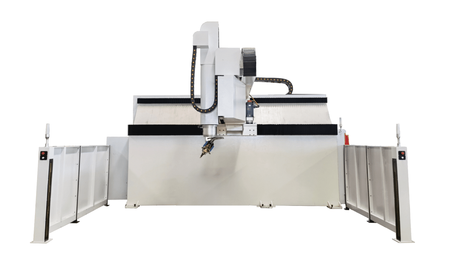
A-axis rotation
Continuous C-axis rotation
Open loading access
01 / Flexible production
Open access for
complex 3D parts.
The SF Series combines a rigid cantilever structure, servo drive and five-axis cutting head in a compact platform designed for convenient loading, programming and maintenance.
- Prototype, trim and cut formed three-dimensional parts.
- Program offline or use manual teaching for application setup.
- Integrate part-specific fixtures on a fixed worktable.
3,000 × 1,400 × 650 mm catalog X/Y/Z travel
Fixed worktable
3,000 × 1,600 × 650 mm catalog X/Y/Z travel
3 / 4 / 6 kW · Fixed worktable
Catalog check: the printed 4025 travel values do not align with the model name. They are reproduced here without correction; confirm the final X/Y/Z envelope with ZG Laser before quotation or publication.
02 / Machine capabilities
Compact structure.
Practical access.
The catalog focuses on accessibility, coordinated five-axis motion, programming flexibility and straightforward daily operation.
Cantilever accessibility
The open cantilever layout supports convenient loading, unloading and access to fixtures. Validate the complete part and clamp envelope before configuration.
Servo-driven rigidity
A high-rigidity machine structure and servo drive provide the mechanical foundation for coordinated high-speed, high-precision five-axis motion.
Continuous-angle head
The A axis rotates ±135°, while the C axis provides N × 360° motion for cutting access from multiple angles around three-dimensional features.
Offline & teach programming
Prepare paths from digital geometry or use manual teaching where appropriate. Confirm software, postprocessor and collision-checking scope in the project agreement.
Collision protection
Multiple anti-collision functions support machine and cutting-head protection. Application-specific fixtures and programs still require careful clearance verification.
Service & expansion ready
Automatic lubrication, a flying optical path, a front control panel and a reserved interface support routine operation and future automation planning.
03 / Catalog applications
Four representative part types.
These samples are taken directly from the SF Series product catalog. Final suitability depends on geometry, material, fixture design and required quality.
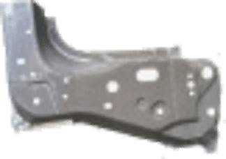
Front lower body rib plate
Multi-angle trimming and hole cutting on a formed structural component, subject to fixture and access validation.
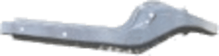
Front longitudinal beam
Contour and opening operations on formed beam geometry for prototypes and flexible-batch applications.

Skid plate
Three-dimensional edge and feature cutting on a long formed panel with part-specific workholding.
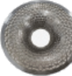
Mesh parts
Cutting patterns and contours on compact formed parts after material, thickness and heat-input review.
Have a different part? Share your geometry and production requirements ↗
04 / Technical specifications
Compare SF configurations.
Use the catalog table as a starting point, then verify the usable envelope, fixture clearance and supplied configuration for the actual project.
On smaller screens, scroll the table horizontally to compare both models.
| Parameter | 3014SF Series | 4025SF Series |
|---|---|---|
| MOTION & TRAVEL | ||
| X-axis travel¹ | 3,000 mm | 3,000 mm |
| Y-axis travel¹ | 1,400 mm | 1,600 mm |
| Z-axis travel | 650 mm | 650 mm |
| A-axis travel | ±135° | ±135° |
| C-axis travel | N × 360° | N × 360° |
| U-axis travel (floating axis) | ±9 mm | ±9 mm |
| SPEED & ACCURACY | ||
| Max. speed, X/Y/Z axes | 80 m/min | 80 m/min |
| Max. speed, A/C axes | 540°/s | 540°/s |
| X/Y/Z-axis machining accuracy² | ±0.05 mm | ±0.05 mm |
| A/C-axis machining accuracy² | 0.015° | 0.015° |
| X/Y/Z-axis repeat positioning accuracy | ±0.03 mm | ±0.03 mm |
| A/C-axis repeat positioning accuracy | 0.01° | 0.01° |
| TABLE, LASER & UTILITIES | ||
| Worktable | Fixed worktable | Fixed worktable |
| Laser power options | 3,000 / 4,000 / 6,000 W | 3,000 / 4,000 / 6,000 W |
| Power requirement | 380 V / 50 Hz | 380 V / 50 Hz |
| Assist gases | Air / Nitrogen / Oxygen | Air / Nitrogen / Oxygen |
| FOOTPRINT & WEIGHT | ||
| Machine footprint | ≈7,600 × 6,500 × 4,000 mm | ≈7,600 × 6,800 × 4,000 mm |
| Machine weight³ | ≈12,000 | ≈12,000 |
² Accuracy values are machine-axis figures, not a guarantee of finished-part tolerance. Results depend on part variation, fixturing, programming and cutting conditions.
³ The catalog prints approximately 12,000 but does not state a weight unit on this row; the value is therefore reproduced without an invented unit.
05 / Project evaluation
Start with the part.
Define the flexible solution.
A practical evaluation sequence turns catalog specifications into a project configuration that can be verified.
Part & process review
Provide a drawing or 3D model, material grade, thickness, target tolerances and output requirements.
Envelope & fixture review
Check the verified travel, fixed-table fixture, head access, laser power and assist-gas requirements.
Sample validation
Agree on trial-cutting conditions and evaluate edge quality, hole geometry and the proposed sequence.
Project definition
Confirm machine scope, utilities, software, automation interfaces, acceptance criteria and support requirements.
06 / Common questions
Before you specify
your SF Series.
The right configuration starts with verified travel data, clear part requirements and an agreed validation method.
How do I choose between SF 3014 and SF 4025?
Start with the complete part-and-fixture envelope, but verify the travel data first. The supplied catalog lists 3,000 × 1,400 mm X/Y travel for 3014 and 3,000 × 1,600 mm for 4025. Because the 4025 entry does not align with the model name, request a confirmed drawing and usable cutting envelope before selection.
When is a cantilever platform useful?
The open structure can make loading, unloading, teaching and fixture access convenient for prototypes and flexible batches. Suitability still depends on part dimensions, center of gravity, workholding, cutting-head reach and required production flow.
What does the fixed worktable mean for production?
Parts and fixtures are loaded onto a fixed table rather than an automatic indexing table. Review ergonomic access, fixture changeover, manual or automated handling and the complete cycle for your planned batch size.
Which laser power should I select?
The catalog lists 3,000 W, 4,000 W and 6,000 W options. The appropriate power depends on material grade, thickness, geometry, assist gas and production targets. A sample cutting evaluation provides a stronger basis than power alone.
Does ±0.05 mm guarantee the finished-part tolerance?
No. The catalog identifies ±0.05 mm as an X/Y/Z-axis machining accuracy figure. Finished-part results also depend on formed-part variation, datum strategy, fixturing, programming and process conditions. Agree on part-level acceptance criteria.
Are offline software and automation interfaces included?
The catalog describes offline programming, manual teaching and a reserved expansion interface as capabilities, but does not define a complete commercial supply scope. Confirm software licensing, postprocessors, interface signals, fixtures and optional hardware in the quotation.
What should I send for a project review?
Provide a 3D model or drawing, material grade and thickness, part dimensions, required contours and holes, target quality, batch size or output per shift, and fixture or handling preferences. You can start with the form below.
07 / Tell us about your part
Turn your part drawing
into a cutting plan.
Describe your component and production goals. ZG Laser can review the geometry and discuss a suitable SF Series configuration.
- Material grade and wall thickness
- 3D geometry and required cutting features
- Target tolerance and output per shift
- Fixture, handling and automation preferences
Prefer to contact the team directly?
Visit our Contact page ↗
Request a project review
Start with the essentials. Fields marked * are required.
For drawings or larger files, describe what you have available and ask the team for the appropriate submission method.