
Built for automotive production
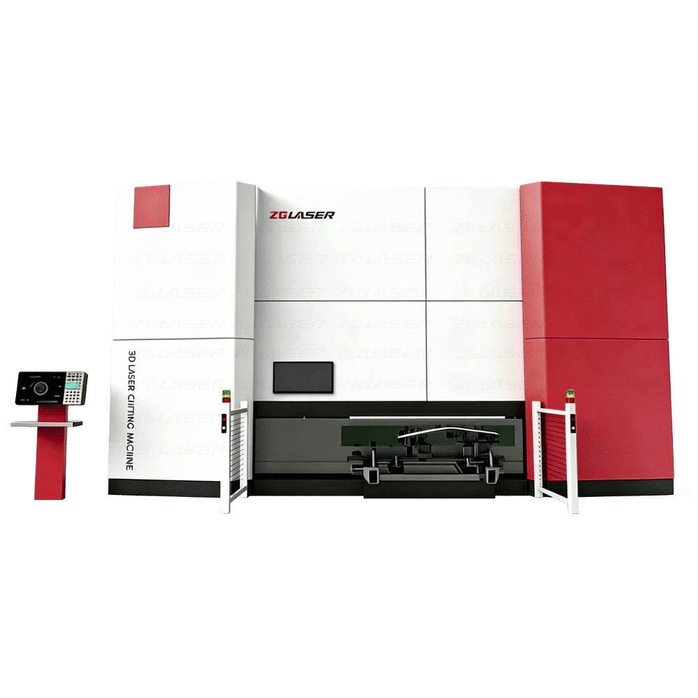
S-Auto Series 3D Five-Axis
Laser Cutting Machine
A dedicated five-axis system for automotive hot-stamped components. Combine edge trimming and hole cutting with a rotary-table production layout.
Laser power options
Complex contours & holes
Multi-station operation
01 / Production focus
Designed around
the automotive part.
The S-Auto Series combines a gantry structure, a 3D cutting head and an automatic rotary table for repeat production of formed metal components.
- Trim edges after forming or hot stamping.
- Cut holes and contours on three-dimensional surfaces.
- Evaluate part access, fixtures and station handling together.
3,500 × 2,100 × 700 mm X/Y/Z travel
4,000 mm rotary table diameter
4,500 × 2,500 × 700 mm X/Y/Z travel
5,000 mm rotary table diameter
Machine travel is not the same as usable part size. Confirm the cutting envelope with the part, fixture and cutting-head clearance.
02 / Machine capabilities
A platform for the full
cutting task.
Motion, workholding and programming need to work together. Configure the system around the part you actually produce.
Dynamic five-axis motion
Coordinated linear and A/C-axis motion supports multi-angle contours. Match motion paths and acceleration settings to the part geometry and required edge quality.
Multi-station production
Use an automatic rotary table to organize the cutting and part-handling sequence. Review station loading, fixture access and the complete cycle together.
Gantry machine structure
A dedicated machine-tool platform provides the foundation for coordinated motion, repeat positioning and part-specific fixturing.
3D laser cutting head
Access angled surfaces with a multi-axis cutting head and floating-axis travel. Check the complete head envelope around clamps and part features.
Offline programming
Prepare the cutting task from a digital part model. Confirm the software scope, machine configuration and collision checks for your project.
Trim and cut in one setup
Evaluate whether edges and holes can be completed within a single fixture setup. Part access and clamp clearance determine the practical process sequence.
03 / Typical applications
Made for formed geometry.
Representative samples from the S-Auto product catalog. Final suitability depends on material, thickness, geometry and quality requirements.
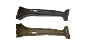
Hot-formed structural parts
Edge trimming and hole cutting for formed automotive structural components after the forming process.
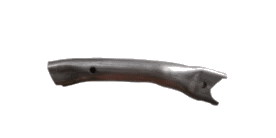
Hydroformed tubes
Contour and opening operations on formed tube geometries, subject to access and fixture verification.
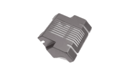
Complex 3D metal parts
Multi-angle trimming and hole cutting on formed panels and irregular three-dimensional workpieces.
Have a different part? Share your geometry and production requirements ↗
04 / Technical specifications
Compare S-Auto configurations.
Select the machine envelope first, then match laser power and supporting options to your application.
On smaller screens, scroll the table horizontally to compare both models.
| Parameter | 3521S-Auto Series | 4525S-Auto Series |
|---|---|---|
| MOTION & TRAVEL | ||
| X-axis travel | 3,500 mm | 4,500 mm |
| Y-axis travel | 2,100 mm | 2,500 mm |
| Z-axis travel | 700 mm | 700 mm |
| A-axis travel | ±135° | ±135° |
| C-axis travel | N × 360° | N × 360° |
| U-axis travel (floating axis) | ±9 mm | ±9 mm |
| SPEED & ACCURACY | ||
| Max. speed, X/Y/Z axes | 100 m/min | 100 m/min |
| Max. speed, A/C axes | 540°/s | 540°/s |
| X/Y/Z-axis machining accuracy¹ | ±0.05 mm | ±0.05 mm |
| A/C-axis machining accuracy¹ | 0.015° | 0.015° |
| X/Y/Z-axis repeat positioning accuracy | ±0.03 mm | ±0.03 mm |
| A/C-axis repeat positioning accuracy | 0.01° | 0.01° |
| TABLE, LASER & POWER | ||
| Worktable | Automatic rotary table | Automatic rotary table |
| Table diameter | 4,000 mm | 5,000 mm |
| Max. load capacity, single side | 350 kg | 500 kg |
| Single positioning time of worktable² | 2.5 s | 2.5 s |
| Laser power options | 3,000 / 4,000 / 6,000 W | 3,000 / 4,000 / 6,000 W |
| Power requirement | 380 V / 50 Hz | 380 V / 50 Hz |
² Worktable positioning time is not the total cutting or production cycle time.
05 / Project evaluation
Start with the part.
Define the production solution.
A practical evaluation sequence helps turn a machine specification into a clear project scope.
Part & process review
Provide a drawing or 3D model, material grade, thickness, target tolerances and output requirements.
Configuration review
Check travel, rotary table capacity, laser power, fixtures and the available cutting envelope.
Sample validation
Agree on trial-cutting conditions and evaluate edge quality, hole geometry and the proposed cycle.
Project definition
Confirm equipment scope, utilities, software, acceptance criteria and support requirements.
06 / Common questions
Before you specify
your S-Auto.
The right configuration starts with clear part requirements and an agreed validation process.
How do I choose between 3521 and 4525?
Start with the full part-and-fixture envelope. The 3521 has 3,500 × 2,100 mm X/Y travel and a 4,000 mm table; the 4525 has 4,500 × 2,500 mm X/Y travel and a 5,000 mm table. Both list 700 mm Z travel. Confirm cutting-head access, fixture clearance and load capacity before choosing.
Which laser power should I select?
The catalog lists 3,000 W, 4,000 W and 6,000 W options. The appropriate power depends on material grade, thickness, geometry, assist gas and production targets. A sample cutting evaluation provides a stronger basis than power alone.
Does ±0.05 mm mean every finished part meets that tolerance?
No. The catalog lists ±0.05 mm as an X/Y/Z-axis machining accuracy figure. Finished-part results also depend on forming variation, datum selection, fixturing, programming and the cutting process. Agree on a part-level acceptance method for your project.
Does the rotary table provide a 2.5-second production cycle?
No. The 2.5-second value is the catalog’s single positioning time for the worktable. Total cycle time also includes cutting, head movement, loading, unloading and any required checks.
Are fixtures and offline software included?
The catalog presents offline software and a rotary table as S-Auto capabilities, but it does not define a complete commercial supply scope. Confirm software licensing, machine models, postprocessors, fixtures and other accessories in the quotation and technical agreement.
What should I send for a project review?
Provide a 3D model or drawing, material grade and thickness, part dimensions, required holes and contours, quality targets, output per shift and loading preferences. Include fixture or datum information if already available. You can first describe the project through the form below.
07 / Tell us about your part
Turn your part drawing
into a cutting plan.
Describe your component and production goals. ZG Laser can review the application and discuss a suitable S-Auto configuration.
- Material grade and wall thickness
- 3D geometry and required cutting features
- Target tolerance and output per shift
- Fixture, handling and automation preferences
Prefer to contact the team directly?
Visit our Contact page ↗
Request a project review
Start with the essentials. Fields marked * are required.
For drawings or larger files, describe what you have available and ask the team for the appropriate submission method.