
Dual servo drive
The catalog specifies a servo dual-drive arrangement for the high-speed gantry. Review the final drive and control configuration in the technical agreement.
Large-format five-axis cutting
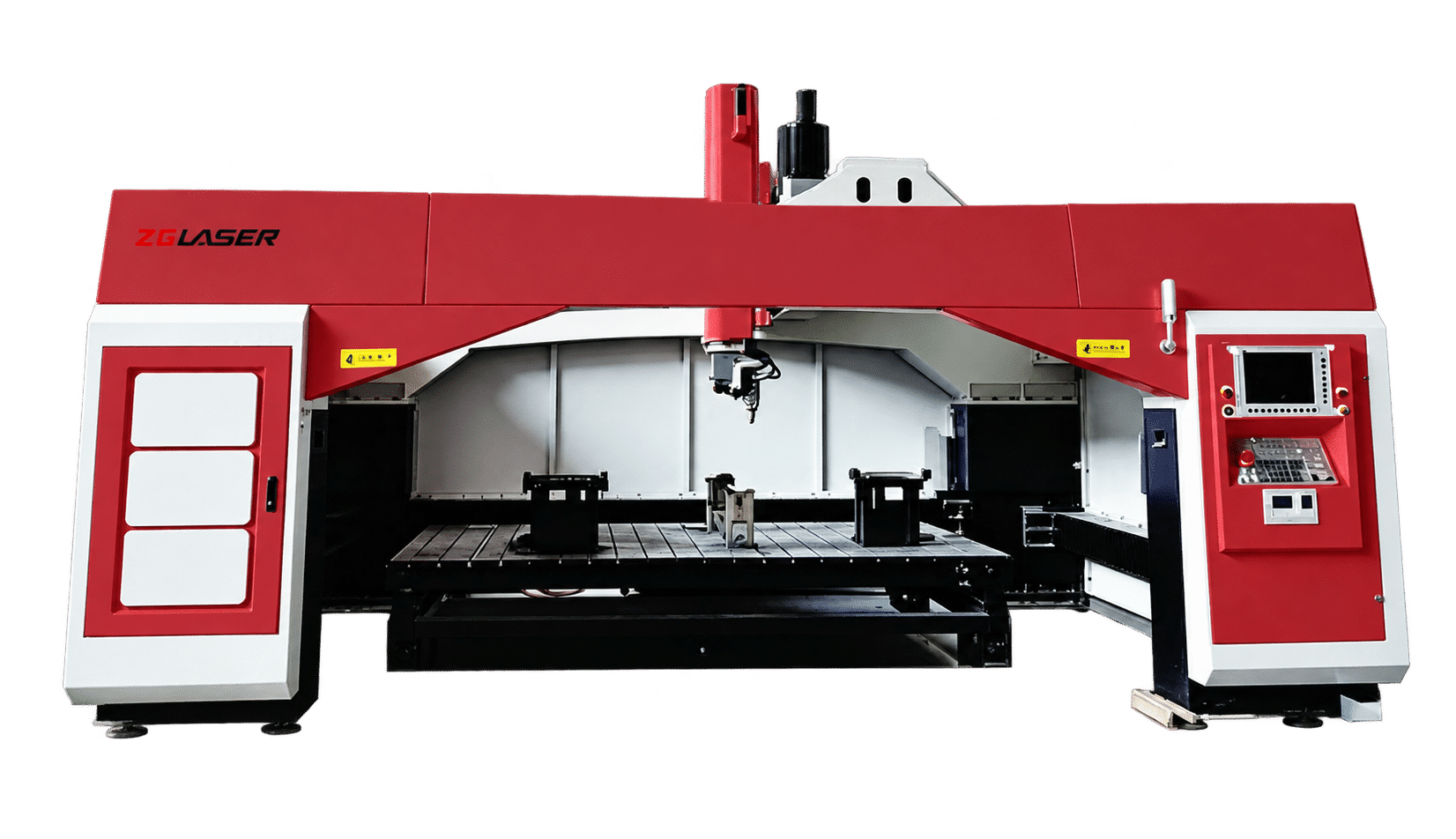
A high-rigidity gantry platform with dual servo drive for large-range cutting across automotive, mold, appliance, machinery, hardware and aerospace applications.
Max. X/Y/Z-axis speed
Laser power options
Fixed or moving slide layout
01 / Production focus
The DF Series combines a gantry structure, dual servo drive and a five-axis cutting head for precise cutting of large formed components and complex three-dimensional workpieces.
4,000 × 2,100 × 680 mm X/Y/Z travel
4,000 × 2,500 × 680 mm X/Y/Z travel
4,500 × 2,500 × 680 mm X/Y/Z travel
Machine travel is not the same as usable part size. Confirm the cutting envelope with the part, fixture, table and cutting-head clearance.
02 / Machine capabilities
Travel, motion, workholding and protection should be specified together around the real production task.
The catalog specifies a servo dual-drive arrangement for the high-speed gantry. Review the final drive and control configuration in the technical agreement.
The gantry machine-tool structure supports stable coordinated motion across the large working range and provides a foundation for part-specific fixturing.
Three model sizes cover X travel from 4,000 to 4,500 mm and Y travel from 2,100 to 2,500 mm, with 680 mm Z travel.
A-axis travel of ±135°, continuous C-axis rotation and ±9 mm floating-axis travel support multi-angle cutting around complex contours.
Select a fixed or moving slide worktable around part size, fixture access, loading method and the intended production sequence.
The brochure presents a fully enclosed housing, dust extraction and moving slide table as configurable options rather than a universal standard scope.
03 / Typical applications
Applications shown in the product catalog and reference product page. Final suitability depends on material, thickness, geometry, access and quality requirements.
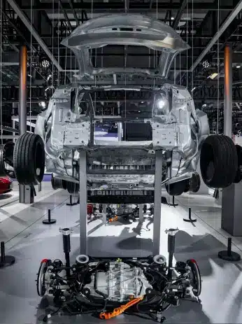
Prototype and trial-part cutting where flexible fixtures and repeatable five-axis access are required.
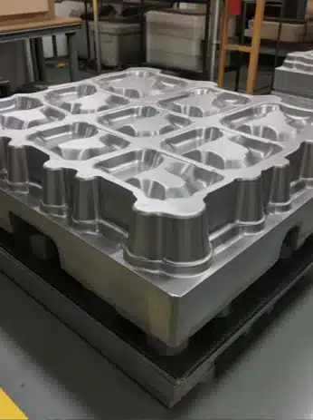
Complex contour and formed-surface work for mold development, verification and related production tasks.
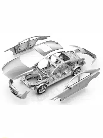
Edge trimming and hole cutting for hot-stamped components after forming.
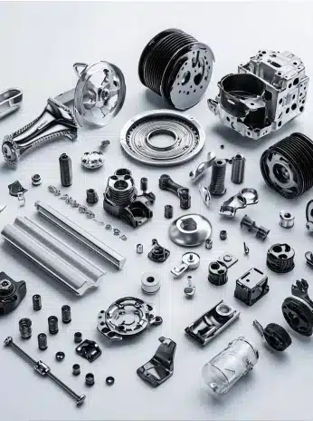
Multi-angle cutting for hardware, profiles, side panels and other three-dimensional metal components.
Have a different part? Share your geometry and production requirements ↗
04 / Machine configuration
The product catalog presents these layouts as options. Final supply scope must be written into the quotation and technical agreement.
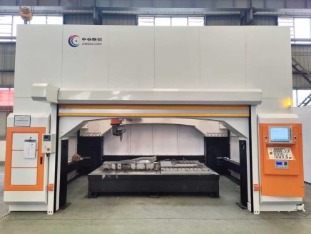
A protective enclosure can be configured around the machine. Confirm the applicable safety standard, observation window, interlocks and final layout.
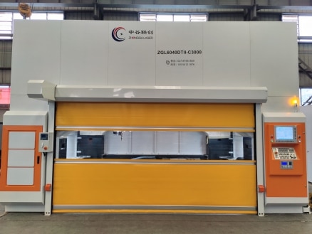
Match extraction capacity and ducting to material, cutting process, enclosure volume and local environmental requirements.
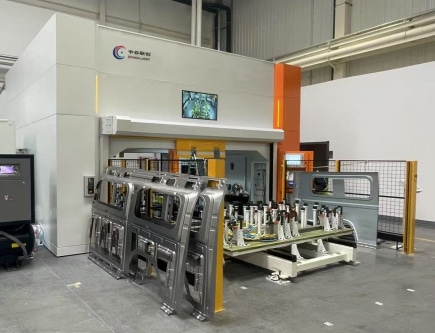
A moving slide table can support offline loading and unloading. Confirm table travel, fixtures, guarding and the complete cycle before ordering.
05 / Technical specifications
Select the working range first, then define the table, enclosure, extraction, laser power and process package.
On smaller screens, scroll the table horizontally to compare all three models.
| Parameter | 4021DF Series | 4025DF Series | 4525DF Series |
|---|---|---|---|
| MOTION & TRAVEL | |||
| X-axis travel | 4,000 mm | 4,000 mm | 4,500 mm |
| Y-axis travel | 2,100 mm | 2,500 mm | 2,500 mm |
| Z-axis travel | 680 mm | 680 mm | 680 mm |
| A-axis travel | ±135° | ±135° | ±135° |
| C-axis travel | N × 360° | N × 360° | N × 360° |
| U-axis travel (floating axis) | ±9 mm | ±9 mm | ±9 mm |
| SPEED & ACCURACY | |||
| Max. speed, X/Y/Z axes | 80 m/min | 80 m/min | 80 m/min |
| Max. speed, A/C axes | 540°/s | 540°/s | 540°/s |
| X/Y/Z-axis machining accuracy¹ | ±0.05 mm | ±0.05 mm | ±0.05 mm |
| A/C-axis machining accuracy¹ | 0.015° | 0.015° | 0.015° |
| X/Y/Z-axis repeat positioning accuracy | ±0.03 mm | ±0.03 mm | ±0.03 mm |
| A/C-axis repeat positioning accuracy | 0.01° | 0.01° | 0.01° |
| TABLE, LASER & UTILITIES | |||
| Worktable | Fixed / slide | Fixed / slide | Fixed / slide |
| Laser power options | 3,000 / 4,000 / 6,000 W | 3,000 / 4,000 / 6,000 W | 3,000 / 4,000 / 6,000 W |
| Power requirement | 380 V / 50 Hz | 380 V / 50 Hz | 380 V / 50 Hz |
| Applicable assist gases | Air / nitrogen / oxygen | Air / nitrogen / oxygen | Air / nitrogen / oxygen |
06 / Project evaluation
A practical evaluation sequence helps turn a machine specification into a clear production scope.
Provide a drawing or 3D model, material grade, thickness, target tolerances and expected output.
Check the complete part-and-fixture envelope, loading direction, worktable layout and cutting-head clearance.
Define enclosure, extraction, assist gas, electrical supply, software and integration requirements.
Validate the process on a representative part, then agree on equipment scope and acceptance criteria.
07 / Common questions
The right configuration starts with the working envelope, loading process and safety requirements.
Start with the full part-and-fixture envelope. The 4021 lists 4,000 × 2,100 mm X/Y travel, the 4025 lists 4,000 × 2,500 mm, and the 4525 lists 4,500 × 2,500 mm. All three list 680 mm Z travel. Confirm cutting-head access and fixture clearance before choosing.
The catalog lists 3,000 W, 4,000 W and 6,000 W options. The appropriate power depends on material grade, thickness, geometry, assist gas and production targets. A sample cutting evaluation provides a stronger basis than power alone.
No. The catalog lists ±0.05 mm as an X/Y/Z-axis machining accuracy figure. Finished-part results also depend on forming variation, datum selection, fixturing, programming and the cutting process. Agree on a part-level acceptance method for your project.
A fixed table can suit straightforward loading and lower-complexity layouts. A moving slide table can support loading and unloading away from the cutting position. The correct choice depends on part size, fixtures, guarding, handling and the complete production cycle.
Not necessarily. The product catalog presents the fully enclosed housing, dust extraction and moving slide table as configuration options. Confirm every included option, interface and safety function in the quotation and technical agreement.
Provide a 3D model or drawing, material grade and thickness, part dimensions, required holes and contours, quality targets, output per shift and loading preferences. Include fixture or datum information if already available. You can first describe the project through the form below.
08 / Tell us about your part
Describe your component, loading method and production goals. ZG Laser can review the application and discuss a suitable DF Series configuration.
Prefer to contact the team directly?
Visit our Contact page ↗
Start with the essentials. Fields marked * are required.
For drawings or larger files, describe what you have available and ask the team for the appropriate submission method.